

237
of CNTs with sizes less than 1 nanometer in diameter would allow
more of these switches to be part of a chip. In an FET, the current
flows through a CNT with semiconductor properties along a
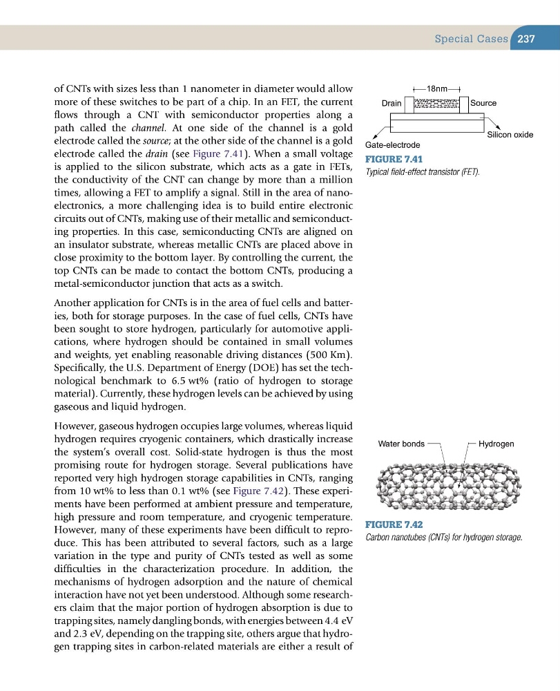
path called the channel. At one side of the channel is a gold
electrode called the source; at the other side of the channel is a gold
electrode called the drain (see Figure 7.41). When a small voltage
is applied to the silicon substrate, which acts as a gate in FETs,
the conductivity of the CNT can change by more than a million
times, allowing a FET to amplify a signal. Still in the area of nanoelectronics, a more challenging idea is to build entire electronic
circuits out of CNTs, making use of their metallic and semiconducting properties. In this case, semiconducting CNTs are aligned on
an insulator substrate, whereas metallic CNTs are placed above in
close proximity to the bottom layer. By controlling the current, the
top CNTs can be made to contact the bottom CNTs, producing a
metal-semiconductor junction that acts as a switch.
Another application for CNTs is in the area of fuel cells and batteries, both for storage purposes. In the case of fuel cells, CNTs have
been sought to store hydrogen, particularly for automotive applications, where hydrogen should be contained in small volumes
and weights, yet enabling reasonable driving distances (500 Km).
Specifically, the U.S. Department of Energy (DOE) has set the technological benchmark to 6.5 wt% (ratio of hydrogen to storage
material). Currently, these hydrogen levels can be achieved by using
gaseous and liquid hydrogen.
However, gaseous hydrogen occupies large volumes, whereas liquid
hydrogen requires cryogenic containers, which drastically increase
the system’s overall cost. Solid-state hydrogen is thus the most
promising route for hydrogen storage. Several publications have
reported very high hydrogen storage capabilities in CNTs, ranging
from 10 wt% to less than 0.1 wt% (see Figure 7.42). These experiments have been performed at ambient pressure and temperature,
high pressure and room temperature, and cryogenic temperature.
However, many of these experiments have been difficult to reproduce. This has been attributed to several factors, such as a large
variation in the type and purity of CNTs tested as well as some
difficulties in the characterization procedure. In addition, the
mechanisms of hydrogen adsorption and the nature of chemical
interaction have not yet been understood. Although some researchers claim that the major portion of hydrogen absorption is due to
trapping sites, namely dangling bonds, with energies between 4.4 eV
and 2.3 eV, depending on the trapping site, others argue that hydrogen trapping sites in carbon-related materials are either a result of
Figure 7.41
Typical field-effect transistor (FET).
18nm
Gate-electrode
Silicon oxide
Drain
Source
Figure 7.42
Carbon nanotubes (CNTs) for hydrogen storage.
Hydrogen
Water bonds
Special Cases
of CNTs with sizes less than 1 nanometer in diameter would allow
more of these switches to be part of a chip. In an FET, the current
flows through a CNT with semiconductor properties along a
path called the channel. At one side of the channel is a gold
electrode called the source; at the other side of the channel is a gold
electrode called the drain (see Figure 7.41). When a small voltage
is applied to the silicon substrate, which acts as a gate in FETs,
the conductivity of the CNT can change by more than a million
times, allowing a FET to amplify a signal. Still in the area of nanoelectronics, a more challenging idea is to build entire electronic
circuits out of CNTs, making use of their metallic and semiconducting properties. In this case, semiconducting CNTs are aligned on
an insulator substrate, whereas metallic CNTs are placed above in
close proximity to the bottom layer. By controlling the current, the
top CNTs can be made to contact the bottom CNTs, producing a
metal-semiconductor junction that acts as a switch.
Another application for CNTs is in the area of fuel cells and batteries, both for storage purposes. In the case of fuel cells, CNTs have
been sought to store hydrogen, particularly for automotive applications, where hydrogen should be contained in small volumes
and weights, yet enabling reasonable driving distances (500 Km).
Specifically, the U.S. Department of Energy (DOE) has set the technological benchmark to 6.5 wt% (ratio of hydrogen to storage
material). Currently, these hydrogen levels can be achieved by using
gaseous and liquid hydrogen.
However, gaseous hydrogen occupies large volumes, whereas liquid
hydrogen requires cryogenic containers, which drastically increase
the system’s overall cost. Solid-state hydrogen is thus the most
promising route for hydrogen storage. Several publications have
reported very high hydrogen storage capabilities in CNTs, ranging
from 10 wt% to less than 0.1 wt% (see Figure 7.42). These experiments have been performed at ambient pressure and temperature,
high pressure and room temperature, and cryogenic temperature.
However, many of these experiments have been difficult to reproduce. This has been attributed to several factors, such as a large
variation in the type and purity of CNTs tested as well as some
difficulties in the characterization procedure. In addition, the
mechanisms of hydrogen adsorption and the nature of chemical
interaction have not yet been understood. Although some researchers claim that the major portion of hydrogen absorption is due to
trapping sites, namely dangling bonds, with energies between 4.4 eV
and 2.3 eV, depending on the trapping site, others argue that hydrogen trapping sites in carbon-related materials are either a result of
Figure 7.41
Typical field-effect transistor (FET).
18nm
Gate-electrode
Silicon oxide
Drain
Source
Figure 7.42
Carbon nanotubes (CNTs) for hydrogen storage.
Hydrogen
Water bonds
Special Cases