

119
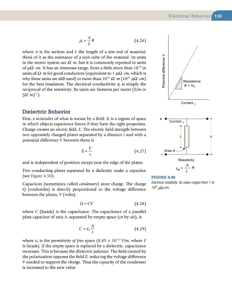
ρ e
A
L
R
=
(4.26)
where A is the section and L the length of a test rod of material;
think of it as the resistance of a unit cube of the material. Its units
in the metric system are Ω·m, but it is commonly reported in units
of µΩ·cm. It has an immense range, from a little more than 10
−8 in
units of Ω·m for good conductors (equivalent to 1 µΩ·cm, which is
why these units are still used) to more than 10
16
Ω·m (10
24
µΩ·cm)
for the best insulators. The electrical conductivity κ e is simply the
reciprocal of the resistivity. Its units are Siemens per meter (S/m or
(Ω·m)
−1 ).
Dielectric Behavior
First, a reminder of what is meant by a field: It is a region of space
in which objects experience forces if they have the right properties.
Charge creates an electric field, E. The electric field strength between
two oppositely charged plates separated by a distance t and with a
potential difference V between them is
E
V
t
=
(4.27)
and is independent of position except near the edge of the plates.
Two conducting plates separated by a dielectric make a capacitor
(see Figure 4.50).
Capacitors (sometimes called condensers) store charge. The charge
Q (coulombs) is directly proportional to the voltage difference
between the plates, V (volts):
Q CV
=
(4.28)
where C (farads) is the capacitance. The capacitance of a parallel
plate capacitor of area A, separated by empty space (or by air), is
C
A
t
o
= ε
(4.29)
where ε o is the permittivity of free space (8.85 × 10
−12 F/m, where F
is farads). If the empty space is replaced by a dielectric, capacitance
increases. This is because the dielectric polarizes. The field created by
the polarization opposes the field E, reducing the voltage difference
V needed to support the charge. Thus the capacity of the condenser
is increased to the new value
Figure 4.49
Electrical resistivity. Its value ranges from 1 to
10
24
µΩ·cm.
V
L
Potential difference V
Current ι
Resistance
R = V/ ι
Current ι
Area A
Resistivity
ρ e =
A
L
R
+
-
Electrical Behavior
ρ e
A
L
R
=
(4.26)
where A is the section and L the length of a test rod of material;
think of it as the resistance of a unit cube of the material. Its units
in the metric system are Ω·m, but it is commonly reported in units
of µΩ·cm. It has an immense range, from a little more than 10
−8 in
units of Ω·m for good conductors (equivalent to 1 µΩ·cm, which is
why these units are still used) to more than 10
16
Ω·m (10
24
µΩ·cm)
for the best insulators. The electrical conductivity κ e is simply the
reciprocal of the resistivity. Its units are Siemens per meter (S/m or
(Ω·m)
−1 ).
Dielectric Behavior
First, a reminder of what is meant by a field: It is a region of space
in which objects experience forces if they have the right properties.
Charge creates an electric field, E. The electric field strength between
two oppositely charged plates separated by a distance t and with a
potential difference V between them is
E
V
t
=
(4.27)
and is independent of position except near the edge of the plates.
Two conducting plates separated by a dielectric make a capacitor
(see Figure 4.50).
Capacitors (sometimes called condensers) store charge. The charge
Q (coulombs) is directly proportional to the voltage difference
between the plates, V (volts):
Q CV
=
(4.28)
where C (farads) is the capacitance. The capacitance of a parallel
plate capacitor of area A, separated by empty space (or by air), is
C
A
t
o
= ε
(4.29)
where ε o is the permittivity of free space (8.85 × 10
−12 F/m, where F
is farads). If the empty space is replaced by a dielectric, capacitance
increases. This is because the dielectric polarizes. The field created by
the polarization opposes the field E, reducing the voltage difference
V needed to support the charge. Thus the capacity of the condenser
is increased to the new value
Figure 4.49
Electrical resistivity. Its value ranges from 1 to
10
24
µΩ·cm.
V
L
Potential difference V
Current ι
Resistance
R = V/ ι
Current ι
Area A
Resistivity
ρ e =
A
L
R
+
-
Electrical Behavior