

C hapter 4 Material Classes, structure, and properties
104
compression in those below. Shafts carry twisting or torsion (d),
which generates shear rather than axial load. Pressure difference
applied to a shell, such as the cylindrical tube shown at (e), generates biaxial tension or compression.
stress
Consider a force F applied as normal to the face of an element of
material, as in Figure 4.30 on the left of row (a) in the figure. The
force is transmitted through the element and balanced by an equal
but opposite force on the other side so that it is in equilibrium (it
does not move). Every plane normal to F carries the force. If the
area of such a plane is A, the tensile stress σ in the element (neglecting its self-weight) is
σ =
F
A
(4.4)
If the sign of F is reversed, the stress is compressive and given a
negative sign. Forces are measured in Newtons (N), so stress has the
dimensions of N/m
2 . But a stress of 1 N/m
2 is tiny—atmospheric
pressure is 10
5 N/m
2 —so the usual unit is MN/m
2 (10
6 N/m
2
),
called megapascals, symbol MPa.
If, instead, the force lies parallel to the face of the element, three
other forces are needed to maintain equilibrium (Figure 4.30b).
They create a state of shear in the element. The shaded plane, for
instance, carries the shear stress τ of
τ =
F
A
s
(4.5)
The units, as before, are MPa.
One further state of multiaxial stress is useful in defining the elastic
response of materials: that produced by applying equal tensile or
compressive forces to all six faces of a cubic element, as in Figure
4.30c. Any plane in the cube now carries the same state of stress; it
is equal to the force on a cube face divided by its area. The state of
stress is one of hydrostatic pressure, symbol p, again with the units
of MPa. There is an unfortunate convention here. Pressures are
positive when they push—the reverse of the convention for simple
tension and compression.
Engineering components can have complex shapes and can be
loaded in many ways, creating complex distributions of stress. But
no matter how complex, the stresses in any small element within the
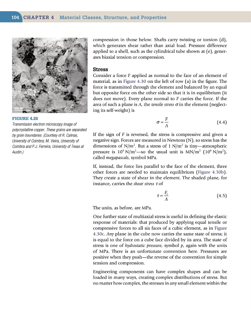
Figure 4.28
Transmission electron microscopy image of
polycrystalline copper. These grains are separated
by grain boundaries. (Courtesy of R. Calinas,
University of Coimbra; M. Vieira, University of
Coimbra and P.J. Ferreira, University of Texas at
Austin.)
104
compression in those below. Shafts carry twisting or torsion (d),
which generates shear rather than axial load. Pressure difference
applied to a shell, such as the cylindrical tube shown at (e), generates biaxial tension or compression.
stress
Consider a force F applied as normal to the face of an element of
material, as in Figure 4.30 on the left of row (a) in the figure. The
force is transmitted through the element and balanced by an equal
but opposite force on the other side so that it is in equilibrium (it
does not move). Every plane normal to F carries the force. If the
area of such a plane is A, the tensile stress σ in the element (neglecting its self-weight) is
σ =
F
A
(4.4)
If the sign of F is reversed, the stress is compressive and given a
negative sign. Forces are measured in Newtons (N), so stress has the
dimensions of N/m
2 . But a stress of 1 N/m
2 is tiny—atmospheric
pressure is 10
5 N/m
2 —so the usual unit is MN/m
2 (10
6 N/m
2
),
called megapascals, symbol MPa.
If, instead, the force lies parallel to the face of the element, three
other forces are needed to maintain equilibrium (Figure 4.30b).
They create a state of shear in the element. The shaded plane, for
instance, carries the shear stress τ of
τ =
F
A
s
(4.5)
The units, as before, are MPa.
One further state of multiaxial stress is useful in defining the elastic
response of materials: that produced by applying equal tensile or
compressive forces to all six faces of a cubic element, as in Figure
4.30c. Any plane in the cube now carries the same state of stress; it
is equal to the force on a cube face divided by its area. The state of
stress is one of hydrostatic pressure, symbol p, again with the units
of MPa. There is an unfortunate convention here. Pressures are
positive when they push—the reverse of the convention for simple
tension and compression.
Engineering components can have complex shapes and can be
loaded in many ways, creating complex distributions of stress. But
no matter how complex, the stresses in any small element within the
Figure 4.28
Transmission electron microscopy image of
polycrystalline copper. These grains are separated
by grain boundaries. (Courtesy of R. Calinas,
University of Coimbra; M. Vieira, University of
Coimbra and P.J. Ferreira, University of Texas at
Austin.)