

84
5 Erosion and Deposition and Their Influence on Plasma …
CFC: CX-2002U
Re-deposition layer
-8Re-deposition layer
20 m
Porous
lamellar
Intrinsic
large pore
CFC: CX-2002U
Re-deposition layer
-8Re-deposition
layer
20 m
Porous
lamellar
Intrinsic
large pore
CFC: CX-2002U
Re-deposition layer
-8Re-deposition layer
20 m
Porous
lamellar
Intrinsic
large pore
Re-deposition
layer
Re-deposition layer
Columnar structures:
oriented parallel to the magnetic
field line (toroidal angle is by
nearly 10 times larger than Bt)
60
CFC:
CX-2002U
20 m
Intrinsic
large pore
Re-deposition layer
Re-deposition layer
Columnar structures:
oriented parallel to the magnetic
field line (toroidal angle is by
nearly 10 times larger than Bt)
60
CFC:
CX-2002U
20 m
Intrinsic
large pore
(a)
(b)
Ordered structure caused by
temperature rise owing to poor
thermal conductivity of porous
deposits
Columnar structure is caused by
deposition from fixed direction
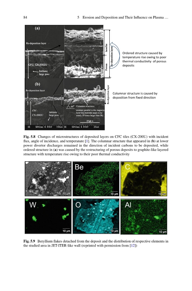
Fig. 5.8 Changes of microstructures of deposited layers on CFC tiles (CX-200U) with incident
flux, angle of incidence, and temperature [1]. The columnar structure that appeared in (b) at lower
power divertor discharges remained in the direction of incident carbons to be deposited, while
ordered structure in (a) was caused by the restructuring of porous deposits to graphite-like layered
structure with temperature rise owing to their poor thermal conductivity
Fig. 5.9 Beryllium flakes detached from the deposit and the distribution of respective elements in
the studied area in JET-ITER-like wall (reprinted with permission from [12])
5 Erosion and Deposition and Their Influence on Plasma …
CFC: CX-2002U
Re-deposition layer
-8Re-deposition layer
20 m
Porous
lamellar
Intrinsic
large pore
CFC: CX-2002U
Re-deposition layer
-8Re-deposition
layer
20 m
Porous
lamellar
Intrinsic
large pore
CFC: CX-2002U
Re-deposition layer
-8Re-deposition layer
20 m
Porous
lamellar
Intrinsic
large pore
Re-deposition
layer
Re-deposition layer
Columnar structures:
oriented parallel to the magnetic
field line (toroidal angle is by
nearly 10 times larger than Bt)
60
CFC:
CX-2002U
20 m
Intrinsic
large pore
Re-deposition layer
Re-deposition layer
Columnar structures:
oriented parallel to the magnetic
field line (toroidal angle is by
nearly 10 times larger than Bt)
60
CFC:
CX-2002U
20 m
Intrinsic
large pore
(a)
(b)
Ordered structure caused by
temperature rise owing to poor
thermal conductivity of porous
deposits
Columnar structure is caused by
deposition from fixed direction
Fig. 5.8 Changes of microstructures of deposited layers on CFC tiles (CX-200U) with incident
flux, angle of incidence, and temperature [1]. The columnar structure that appeared in (b) at lower
power divertor discharges remained in the direction of incident carbons to be deposited, while
ordered structure in (a) was caused by the restructuring of porous deposits to graphite-like layered
structure with temperature rise owing to their poor thermal conductivity
Fig. 5.9 Beryllium flakes detached from the deposit and the distribution of respective elements in
the studied area in JET-ITER-like wall (reprinted with permission from [12])