

9.4 Fuel Retention in Carbon Materials
165
Crystallites (Fillers) are
partly saturated
a
b
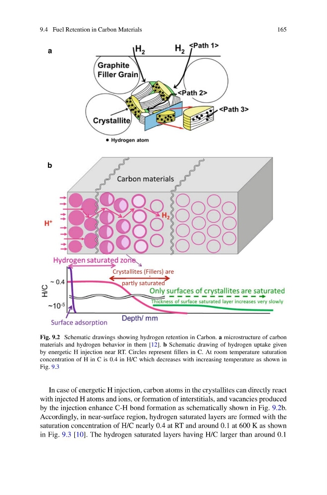
Fig. 9.2 Schematic drawings showing hydrogen retention in Carbon. a microstructure of carbon
materials and hydrogen behavior in them [12]. b Schematic drawing of hydrogen uptake given
by energetic H injection near RT. Circles represent fillers in C. At room temperature saturation
concentration of H in C is 0.4 in H/C which decreases with increasing temperature as shown in
Fig. 9.3
In case of energetic H injection, carbon atoms in the crystallites can directly react
with injected H atoms and ions, or formation of interstitials, and vacancies produced
by the injection enhance C-H bond formation as schematically shown in Fig. 9.2b.
Accordingly, in near-surface region, hydrogen saturated layers are formed with the
saturation concentration of H/C nearly 0.4 at RT and around 0.1 at 600 K as shown
in Fig. 9.3 [10]. The hydrogen saturated layers having H/C larger than around 0.1
165
Crystallites (Fillers) are
partly saturated
a
b
Fig. 9.2 Schematic drawings showing hydrogen retention in Carbon. a microstructure of carbon
materials and hydrogen behavior in them [12]. b Schematic drawing of hydrogen uptake given
by energetic H injection near RT. Circles represent fillers in C. At room temperature saturation
concentration of H in C is 0.4 in H/C which decreases with increasing temperature as shown in
Fig. 9.3
In case of energetic H injection, carbon atoms in the crystallites can directly react
with injected H atoms and ions, or formation of interstitials, and vacancies produced
by the injection enhance C-H bond formation as schematically shown in Fig. 9.2b.
Accordingly, in near-surface region, hydrogen saturated layers are formed with the
saturation concentration of H/C nearly 0.4 at RT and around 0.1 at 600 K as shown
in Fig. 9.3 [10]. The hydrogen saturated layers having H/C larger than around 0.1