

15 In-flight Icing: Modeling, Prediction, and Uncertainty
479
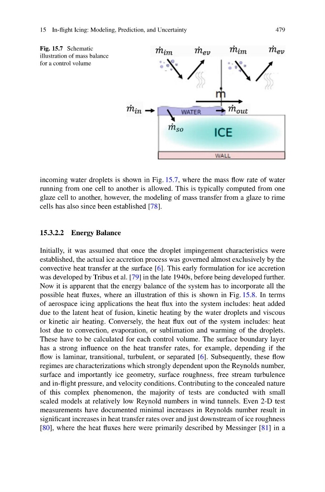
Fig. 15.7 Schematic
illustration of mass balance
for a control volume
incoming water droplets is shown in Fig. 15.7, where the mass flow rate of water
running from one cell to another is allowed. This is typically computed from one
glaze cell to another, however, the modeling of mass transfer from a glaze to rime
cells has also since been established [78].
15.3.2.2 Energy Balance
Initially, it was assumed that once the droplet impingement characteristics were
established, the actual ice accretion process was governed almost exclusively by the
convective heat transfer at the surface [6]. This early formulation for ice accretion
was developed by Tribus et al. [79] in the late 1940s, before being developed further.
Now it is apparent that the energy balance of the system has to incorporate all the
possible heat fluxes, where an illustration of this is shown in Fig. 15.8. In terms
of aerospace icing applications the heat flux into the system includes: heat added
due to the latent heat of fusion, kinetic heating by the water droplets and viscous
or kinetic air heating. Conversely, the heat flux out of the system includes: heat
lost due to convection, evaporation, or sublimation and warming of the droplets.
These have to be calculated for each control volume. The surface boundary layer
has a strong influence on the heat transfer rates, for example, depending if the
flow is laminar, transitional, turbulent, or separated [6]. Subsequently, these flow
regimes are characterizations which strongly dependent upon the Reynolds number,
surface and importantly ice geometry, surface roughness, free stream turbulence
and in-flight pressure, and velocity conditions. Contributing to the concealed nature
of this complex phenomenon, the majority of tests are conducted with small
scaled models at relatively low Reynold numbers in wind tunnels. Even 2-D test
measurements have documented minimal increases in Reynolds number result in
significant increases in heat transfer rates over and just downstream of ice roughness
[80], where the heat fluxes here were primarily described by Messinger [81] in a
479
Fig. 15.7 Schematic
illustration of mass balance
for a control volume
incoming water droplets is shown in Fig. 15.7, where the mass flow rate of water
running from one cell to another is allowed. This is typically computed from one
glaze cell to another, however, the modeling of mass transfer from a glaze to rime
cells has also since been established [78].
15.3.2.2 Energy Balance
Initially, it was assumed that once the droplet impingement characteristics were
established, the actual ice accretion process was governed almost exclusively by the
convective heat transfer at the surface [6]. This early formulation for ice accretion
was developed by Tribus et al. [79] in the late 1940s, before being developed further.
Now it is apparent that the energy balance of the system has to incorporate all the
possible heat fluxes, where an illustration of this is shown in Fig. 15.8. In terms
of aerospace icing applications the heat flux into the system includes: heat added
due to the latent heat of fusion, kinetic heating by the water droplets and viscous
or kinetic air heating. Conversely, the heat flux out of the system includes: heat
lost due to convection, evaporation, or sublimation and warming of the droplets.
These have to be calculated for each control volume. The surface boundary layer
has a strong influence on the heat transfer rates, for example, depending if the
flow is laminar, transitional, turbulent, or separated [6]. Subsequently, these flow
regimes are characterizations which strongly dependent upon the Reynolds number,
surface and importantly ice geometry, surface roughness, free stream turbulence
and in-flight pressure, and velocity conditions. Contributing to the concealed nature
of this complex phenomenon, the majority of tests are conducted with small
scaled models at relatively low Reynold numbers in wind tunnels. Even 2-D test
measurements have documented minimal increases in Reynolds number result in
significant increases in heat transfer rates over and just downstream of ice roughness
[80], where the heat fluxes here were primarily described by Messinger [81] in a