

476
B. Arizmendi et al.
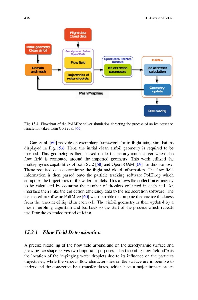
Fig. 15.6 Flowchart of the PoliMIce solver simulation depicting the process of an ice accretion
simulation taken from Gori et al. [60]
Gori et al. [60] provide an exemplary framework for in-flight icing simulations
displayed in Fig. 15.6. Here, the initial clean airfoil geometry is required to be
meshed. This geometry is then passed on to the aerodynamic solver where the
flow field is computed around the imported geometry. This work utilized the
multi-physics capabilities of both SU2 [68] and OpenFOAM [69] for this purpose.
These required data determining the flight and cloud information. The flow field
information is then passed onto the particle tracking software PoliDrop which
computes the trajectories of the water droplets. This allows the collection efficiency
to be calculated by counting the number of droplets collected in each cell. An
interface then links the collection efficiency data to the ice accretion software. The
ice accretion software PoliMIce [60] was then able to compute the new ice thickness
from the amount of liquid in each cell. The airfoil geometry is then updated by a
mesh morphing algorithm and fed back to the start of the process which repeats
itself for the extended period of icing.
15.3.1 Flow Field Determination
A precise modeling of the flow field around and on the aerodynamic surface and
growing ice shape serves two important purposes. The incoming flow field affects
the location of the impinging water droplets due to its influence on the particles
trajectories, while the viscous flow characteristics on the surface are imperative to
understand the convective heat transfer fluxes, which have a major impact on ice
B. Arizmendi et al.
Fig. 15.6 Flowchart of the PoliMIce solver simulation depicting the process of an ice accretion
simulation taken from Gori et al. [60]
Gori et al. [60] provide an exemplary framework for in-flight icing simulations
displayed in Fig. 15.6. Here, the initial clean airfoil geometry is required to be
meshed. This geometry is then passed on to the aerodynamic solver where the
flow field is computed around the imported geometry. This work utilized the
multi-physics capabilities of both SU2 [68] and OpenFOAM [69] for this purpose.
These required data determining the flight and cloud information. The flow field
information is then passed onto the particle tracking software PoliDrop which
computes the trajectories of the water droplets. This allows the collection efficiency
to be calculated by counting the number of droplets collected in each cell. An
interface then links the collection efficiency data to the ice accretion software. The
ice accretion software PoliMIce [60] was then able to compute the new ice thickness
from the amount of liquid in each cell. The airfoil geometry is then updated by a
mesh morphing algorithm and fed back to the start of the process which repeats
itself for the extended period of icing.
15.3.1 Flow Field Determination
A precise modeling of the flow field around and on the aerodynamic surface and
growing ice shape serves two important purposes. The incoming flow field affects
the location of the impinging water droplets due to its influence on the particles
trajectories, while the viscous flow characteristics on the surface are imperative to
understand the convective heat transfer fluxes, which have a major impact on ice