

7.5. NANOCARBON FERROMAGNETS
179
4
h
$ 3
-8000
4ooo
0
4000
8000
MAGNETIC FIELD (Oe)
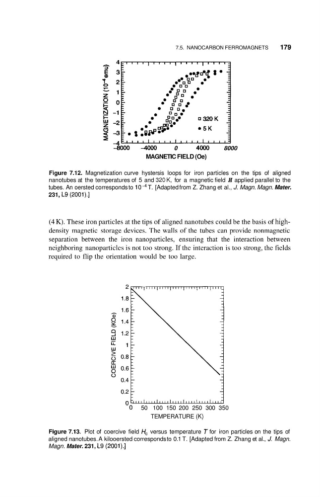
Figure 7.12. Magnetization curve hystersis loops for iron particles on the tips of aligned
nanotubes at the temperatures of 5 and 320K, for a magnetic field H applied parallel to the
tubes. An oersted corresponds to
T. [Adapted from Z. Zhang et al., J. Magn. Magn. Mater.
231, L9 (2001).]
(4 K). These iron particles at the tips of aligned nanotubes could be the basis of highdensity magnetic storage devices. The walls of the tubes can provide nonmagnetic
separation between the iron nanoparticles, ensuring that the interaction between
neighboring nanoparticles is not too strong. If the interaction is too strong, the fields
required to flip the orientation would be too large.
' 0
50 100 150 200 250 300 350
TEMPERATURE (K)
Figure 7.13. Plot of coercive field H, versus temperature T for iron particles on the tips of
aligned nanotubes. A kilooersted corresponds to 0.1 T. [Adapted from Z. Zhang et al., J. Magn.
Magn. Mater. 231, L9 (2001).]
179
4
h
$ 3
-8000
4ooo
0
4000
8000
MAGNETIC FIELD (Oe)
Figure 7.12. Magnetization curve hystersis loops for iron particles on the tips of aligned
nanotubes at the temperatures of 5 and 320K, for a magnetic field H applied parallel to the
tubes. An oersted corresponds to
T. [Adapted from Z. Zhang et al., J. Magn. Magn. Mater.
231, L9 (2001).]
(4 K). These iron particles at the tips of aligned nanotubes could be the basis of highdensity magnetic storage devices. The walls of the tubes can provide nonmagnetic
separation between the iron nanoparticles, ensuring that the interaction between
neighboring nanoparticles is not too strong. If the interaction is too strong, the fields
required to flip the orientation would be too large.
' 0
50 100 150 200 250 300 350
TEMPERATURE (K)
Figure 7.13. Plot of coercive field H, versus temperature T for iron particles on the tips of
aligned nanotubes. A kilooersted corresponds to 0.1 T. [Adapted from Z. Zhang et al., J. Magn.
Magn. Mater. 231, L9 (2001).]