

E1C12 09/14/2010
13:54:15 Page 557
Recall that taking a derivative in time space is multiplying by s in Laplace transform space, and
integrating in time space is dividing by s in Laplace transform space. The choice of gains for the
control actions, k p ; k I ; and k D , is a challenging task and one for which much theory has been
established (7). However, for our purposes we only wish to demonstrate the possible improvement in
the system performance.
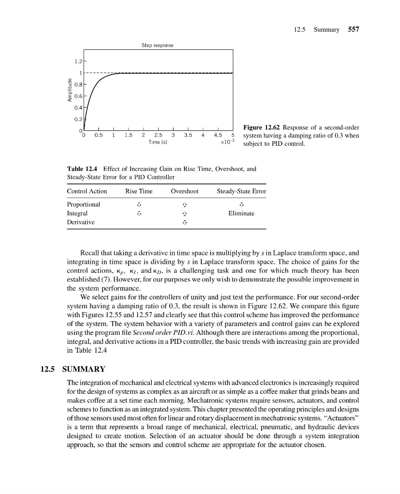
We select gains for the controllers of unity and just test the performance. For our second-order
system having a damping ratio of 0.3, the result is shown in Figure 12.62. We compare this figure
with Figures 12.55 and 12.57 and clearly see that this control scheme has improved the performance
of the system. The system behavior with a variety of parameters and control gains can be explored
using the program file Second order PID.vi. Although there are interactions among the proportional,
integral, and derivative actions in a PID controller, the basic trends with increasing gain are provided
in Table 12.4
12.5 SUMMARY
The integration of mechanical and electrical systems with advanced electronics is increasingly required
for the design of systems as complex as an aircraft or as simple as a coffee maker that grinds beans and
makes coffee at a set time each morning. Mechatronic systems require sensors, actuators, and control
schemes to function as an integrated system. This chapter presented the operating principles and designs
of those sensors used most often for linear and rotary displacement in mechatronic systems. ‘‘Actuators’’
is a term that represents a broad range of mechanical, electrical, pneumatic, and hydraulic devices
designed to create motion. Selection of an actuator should be done through a system integration
approach, so that the sensors and control scheme are appropriate for the actuator chosen.
0
0.2
0.4
0.6
0.8
1
1.2
5
4.5
4
3.5
3
2.5
2
1.5
1
0.5
0
Time (s)
×10
–3
Step response
Amplitude
Figure 12.62 Response of a second-order
system having a damping ratio of 0.3 when
subject to PID control.
Table 12.4 Effect of Increasing Gain on Rise Time, Overshoot, and
Steady-State Error for a PID Controller
Control Action
Rise Time
Overshoot
Steady-State Error
Proportional
%
%
%
Integral
%
%
Eliminate
Derivative
%
12.5 Summary 557
13:54:15 Page 557
Recall that taking a derivative in time space is multiplying by s in Laplace transform space, and
integrating in time space is dividing by s in Laplace transform space. The choice of gains for the
control actions, k p ; k I ; and k D , is a challenging task and one for which much theory has been
established (7). However, for our purposes we only wish to demonstrate the possible improvement in
the system performance.
We select gains for the controllers of unity and just test the performance. For our second-order
system having a damping ratio of 0.3, the result is shown in Figure 12.62. We compare this figure
with Figures 12.55 and 12.57 and clearly see that this control scheme has improved the performance
of the system. The system behavior with a variety of parameters and control gains can be explored
using the program file Second order PID.vi. Although there are interactions among the proportional,
integral, and derivative actions in a PID controller, the basic trends with increasing gain are provided
in Table 12.4
12.5 SUMMARY
The integration of mechanical and electrical systems with advanced electronics is increasingly required
for the design of systems as complex as an aircraft or as simple as a coffee maker that grinds beans and
makes coffee at a set time each morning. Mechatronic systems require sensors, actuators, and control
schemes to function as an integrated system. This chapter presented the operating principles and designs
of those sensors used most often for linear and rotary displacement in mechatronic systems. ‘‘Actuators’’
is a term that represents a broad range of mechanical, electrical, pneumatic, and hydraulic devices
designed to create motion. Selection of an actuator should be done through a system integration
approach, so that the sensors and control scheme are appropriate for the actuator chosen.
0
0.2
0.4
0.6
0.8
1
1.2
5
4.5
4
3.5
3
2.5
2
1.5
1
0.5
0
Time (s)
×10
–3
Step response
Amplitude
Figure 12.62 Response of a second-order
system having a damping ratio of 0.3 when
subject to PID control.
Table 12.4 Effect of Increasing Gain on Rise Time, Overshoot, and
Steady-State Error for a PID Controller
Control Action
Rise Time
Overshoot
Steady-State Error
Proportional
%
%
%
Integral
%
%
Eliminate
Derivative
%
12.5 Summary 557