

E1C12 09/14/2010
13:54:9 Page 512
cosine functions, and that by analyzing a measuring system response to a periodic waveform input
we can discern the allowable range of frequency inputs.
Consider an input to our seismic instrument such that the displacement of the housing is a sine wave,
y hs ¼ Asinvt, and the absolute value of the resulting acceleration of the housing is Av
2 sinvt. If we
consider a free-body diagram of the seismic mass, the spring force and the damping force must balance
the inertial force for the mass. (Notice that gravitational effects could play an important role in the analysis
of this instrument, for instance, if the instrument were installed in an aircraft.) The spring force and
damping force are proportional to the relative displacement and velocity between the housing and the
mass, whereas the inertial force is dependent only on the absolute acceleration of the seismic mass.
We define a relative displacement, y r , as the difference between the housing displacement, y hs ,
and the displacement of the seismic mass, y m , given by
y r ¼ y m À y hs
ð12:1Þ
Newton’s second law may then be expressed
m
d
2
y m
dt 2 þ c
dy r
dt
þ ky r ¼ 0
ð12:2Þ
Substituting Equation 12.1 into Equation 12.2 yields
m
d
2
y hs
dt 2 þ
d
2
y r
dt 2
þ c
dy r
dt
þ ky r ¼ 0
ð12:3Þ
But we know that y hs ¼ A sin vt and
d
2
y hs
dt 2 ¼ ÀAv
2 sin vt
ð12:4Þ
Thus,
m
d
2
y r
dt 2 þ c
dy r
dt
þ ky r ¼ mAv
2 sin vt
ð12:5Þ
This equation is identical in form to Equation 3.12. As in the development for a second-order system
response, we examine the steady-state solution to this governing equation. The transducer senses the
relative motion between the seismic mass and the instrument housing. Thus, for the instrument to be
effective, the value of y r must provide indication of the desired output.
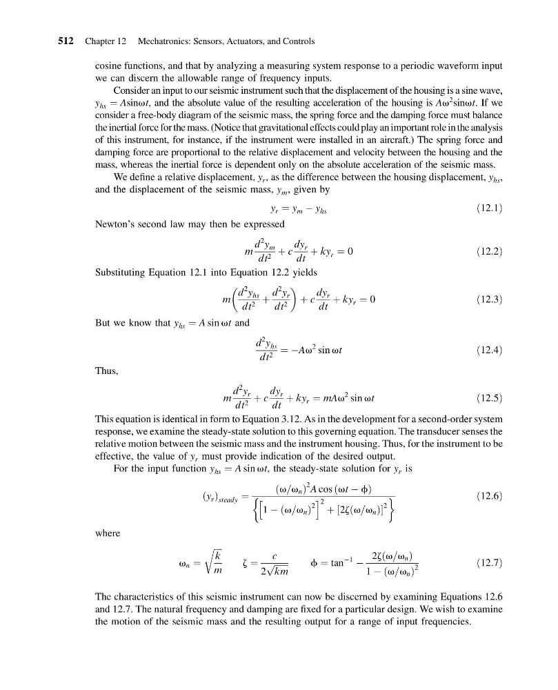
For the input function y hs ¼ A sin vt, the steady-state solution for y r is
y r
ð Þ steady ¼
v=v n
ð
Þ
2 A cos vt À f
ð
Þ
1 À v=v n
ð
Þ
2
h
i 2 þ 2z v=v n
ð
Þ
½
2
&
'
ð12:6Þ
where
v n ¼
ffiffiffiffi
k
m
r
z ¼
c
2
ffiffiffiffiffiffi ffi
km
p
f ¼ tan
À1
À
2z v=v n
ð
Þ
1 À v=v n
ð
Þ
2
ð12:7Þ
The characteristics of this seismic instrument can now be discerned by examining Equations 12.6
and 12.7. The natural frequency and damping are fixed for a particular design. We wish to examine
the motion of the seismic mass and the resulting output for a range of input frequencies.
512 Chapter 12 Mechatronics: Sensors, Actuators, and Controls
13:54:9 Page 512
cosine functions, and that by analyzing a measuring system response to a periodic waveform input
we can discern the allowable range of frequency inputs.
Consider an input to our seismic instrument such that the displacement of the housing is a sine wave,
y hs ¼ Asinvt, and the absolute value of the resulting acceleration of the housing is Av
2 sinvt. If we
consider a free-body diagram of the seismic mass, the spring force and the damping force must balance
the inertial force for the mass. (Notice that gravitational effects could play an important role in the analysis
of this instrument, for instance, if the instrument were installed in an aircraft.) The spring force and
damping force are proportional to the relative displacement and velocity between the housing and the
mass, whereas the inertial force is dependent only on the absolute acceleration of the seismic mass.
We define a relative displacement, y r , as the difference between the housing displacement, y hs ,
and the displacement of the seismic mass, y m , given by
y r ¼ y m À y hs
ð12:1Þ
Newton’s second law may then be expressed
m
d
2
y m
dt 2 þ c
dy r
dt
þ ky r ¼ 0
ð12:2Þ
Substituting Equation 12.1 into Equation 12.2 yields
m
d
2
y hs
dt 2 þ
d
2
y r
dt 2
þ c
dy r
dt
þ ky r ¼ 0
ð12:3Þ
But we know that y hs ¼ A sin vt and
d
2
y hs
dt 2 ¼ ÀAv
2 sin vt
ð12:4Þ
Thus,
m
d
2
y r
dt 2 þ c
dy r
dt
þ ky r ¼ mAv
2 sin vt
ð12:5Þ
This equation is identical in form to Equation 3.12. As in the development for a second-order system
response, we examine the steady-state solution to this governing equation. The transducer senses the
relative motion between the seismic mass and the instrument housing. Thus, for the instrument to be
effective, the value of y r must provide indication of the desired output.
For the input function y hs ¼ A sin vt, the steady-state solution for y r is
y r
ð Þ steady ¼
v=v n
ð
Þ
2 A cos vt À f
ð
Þ
1 À v=v n
ð
Þ
2
h
i 2 þ 2z v=v n
ð
Þ
½
2
&
'
ð12:6Þ
where
v n ¼
ffiffiffiffi
k
m
r
z ¼
c
2
ffiffiffiffiffiffi ffi
km
p
f ¼ tan
À1
À
2z v=v n
ð
Þ
1 À v=v n
ð
Þ
2
ð12:7Þ
The characteristics of this seismic instrument can now be discerned by examining Equations 12.6
and 12.7. The natural frequency and damping are fixed for a particular design. We wish to examine
the motion of the seismic mass and the resulting output for a range of input frequencies.
512 Chapter 12 Mechatronics: Sensors, Actuators, and Controls