

E1C11 09/14/2010
13:14:7 Page 501
11.15 A rectangular bar is instrumented with strain gauges and subjected to a state of uniaxial tension.
The bar has a cross-sectional area of 2 in.
2 , and the bar is 12 in. long. The two strain gauges
are mounted such that one senses the axial strain, while the other senses the lateral strain. For an
axial load of 1500 lb, the axial strain is measured as 1500 me (min./in.), and the lateral gauge
indicates a strain of À465 me. Determine the modulus of elasticity and Poisson’s ratio for this
material.
11.16 A round member having a cross-sectional area of 3 cm
2 experiences an axial load of 10 kN. Two
strain gauges are mounted on the member, one measuring an axial strain of 600 me (m/m), and the
other measuring a lateral strain of À163 me. Determine the modulus of elasticity and Poisson’s ratio
for this material.
11.17 Show that the use of a dummy gauge together with a single active gauge compensates for
temperature but not for bending. Consider the case in which the active gauge is subjected to axial
loading with minimal bending and both gauges experience the same temperature.
11.18 Show that four strain gauges mounted to a shaft such that the gauge pairs measure equal and opposite
strain can be used to measure torsional twist (as suggested in Table 11.1). Show that this method
compensates for axial and bending strains and for temperature.
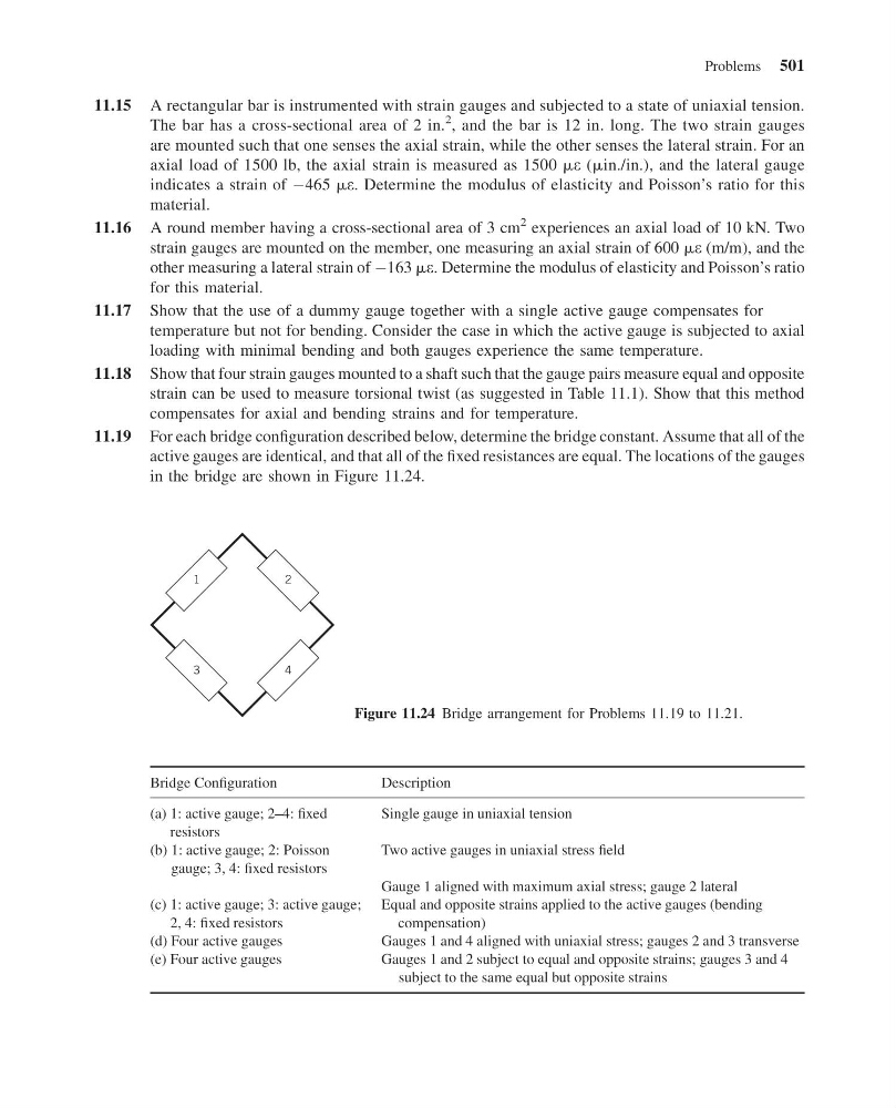
11.19 For each bridge configuration described below, determine the bridge constant. Assume that all of the
active gauges are identical, and that all of the fixed resistances are equal. The locations of the gauges
in the bridge are shown in Figure 11.24.
Bridge Configuration
Description
(a) 1: active gauge; 2–4: fixed
resistors
Single gauge in uniaxial tension
(b) 1: active gauge; 2: Poisson
gauge; 3, 4: fixed resistors
Two active gauges in uniaxial stress field
Gauge 1 aligned with maximum axial stress; gauge 2 lateral
(c) 1: active gauge; 3: active gauge;
2, 4: fixed resistors
Equal and opposite strains applied to the active gauges (bending
compensation)
(d) Four active gauges
Gauges 1 and 4 aligned with uniaxial stress; gauges 2 and 3 transverse
(e) Four active gauges
Gauges 1 and 2 subject to equal and opposite strains; gauges 3 and 4
subject to the same equal but opposite strains
1
2
3
4
Figure 11.24 Bridge arrangement for Problems 11.19 to 11.21.
Problems 501
13:14:7 Page 501
11.15 A rectangular bar is instrumented with strain gauges and subjected to a state of uniaxial tension.
The bar has a cross-sectional area of 2 in.
2 , and the bar is 12 in. long. The two strain gauges
are mounted such that one senses the axial strain, while the other senses the lateral strain. For an
axial load of 1500 lb, the axial strain is measured as 1500 me (min./in.), and the lateral gauge
indicates a strain of À465 me. Determine the modulus of elasticity and Poisson’s ratio for this
material.
11.16 A round member having a cross-sectional area of 3 cm
2 experiences an axial load of 10 kN. Two
strain gauges are mounted on the member, one measuring an axial strain of 600 me (m/m), and the
other measuring a lateral strain of À163 me. Determine the modulus of elasticity and Poisson’s ratio
for this material.
11.17 Show that the use of a dummy gauge together with a single active gauge compensates for
temperature but not for bending. Consider the case in which the active gauge is subjected to axial
loading with minimal bending and both gauges experience the same temperature.
11.18 Show that four strain gauges mounted to a shaft such that the gauge pairs measure equal and opposite
strain can be used to measure torsional twist (as suggested in Table 11.1). Show that this method
compensates for axial and bending strains and for temperature.
11.19 For each bridge configuration described below, determine the bridge constant. Assume that all of the
active gauges are identical, and that all of the fixed resistances are equal. The locations of the gauges
in the bridge are shown in Figure 11.24.
Bridge Configuration
Description
(a) 1: active gauge; 2–4: fixed
resistors
Single gauge in uniaxial tension
(b) 1: active gauge; 2: Poisson
gauge; 3, 4: fixed resistors
Two active gauges in uniaxial stress field
Gauge 1 aligned with maximum axial stress; gauge 2 lateral
(c) 1: active gauge; 3: active gauge;
2, 4: fixed resistors
Equal and opposite strains applied to the active gauges (bending
compensation)
(d) Four active gauges
Gauges 1 and 4 aligned with uniaxial stress; gauges 2 and 3 transverse
(e) Four active gauges
Gauges 1 and 2 subject to equal and opposite strains; gauges 3 and 4
subject to the same equal but opposite strains
1
2
3
4
Figure 11.24 Bridge arrangement for Problems 11.19 to 11.21.
Problems 501