

E1C11 09/14/2010
13:14:7 Page 500
1-cm
2 aluminum rod, with E m = 70 GPa. The gauge senses axial strain. The bridge output is 1 mV for
a bridge input of 5 V. What is the applied load, assuming the rod is in uniaxial tension?
11.9 Suppose the bridge in Problem 11.8 was operated in balanced mode. What change in resistance
would be required to balance the bridge? Assume the loading conditions are the same.
11.10 Consider a structural member subject to loads that produce both axial and bending stresses, as shown
in Figure 11.13. Two strain gauges are to be mounted on the member and connected in a Wheatstone
bridge in such a way that the bridge output indicates the axial component of strain only (the
installation is bending compensated). Show that the installation of the gauges shown in Figure 11.13
will not be sensitive to bending.
11.11 A steel beam member (y p = 0.3) is subjected to simple axial tensile loading. One strain gauge
aligned with the axial load is mounted on the top and center of the beam. A second gauge is similarly
mounted on the bottom of the beam. If the gauges are connected as arms 1 and 4 in a Wheatstone
bridge (Fig. 11.12), determine the bridge constant for this installation. Is the measurement system
temperature compensated? (explain why or why not.) If dE 0 ¼ 10 mV and E i = 10 V, determine the
axial and transverse strains. The gauge factor for each gauge is 2, and all resistances are initially
equal to 120 V.
11.12 An axial strain gauge and a transverse strain gauge are mounted to the top surface of a steel beam
that experiences a uniaxial stress of 2222 psi. The gauges are connected to arms 1 and 2 (Fig. 11.12)
of a Wheatstone bridge. With a purely axial load applied, determine the bridge constant for the
measurement system. If dE 0 ¼ 250mV and E i = 10 V, estimate the average gauge factor of the strain
gauges. For this material, Poisson’s ratio is 0.3 and the modulus of elasticity is 29:4 Â 10
6 psi.
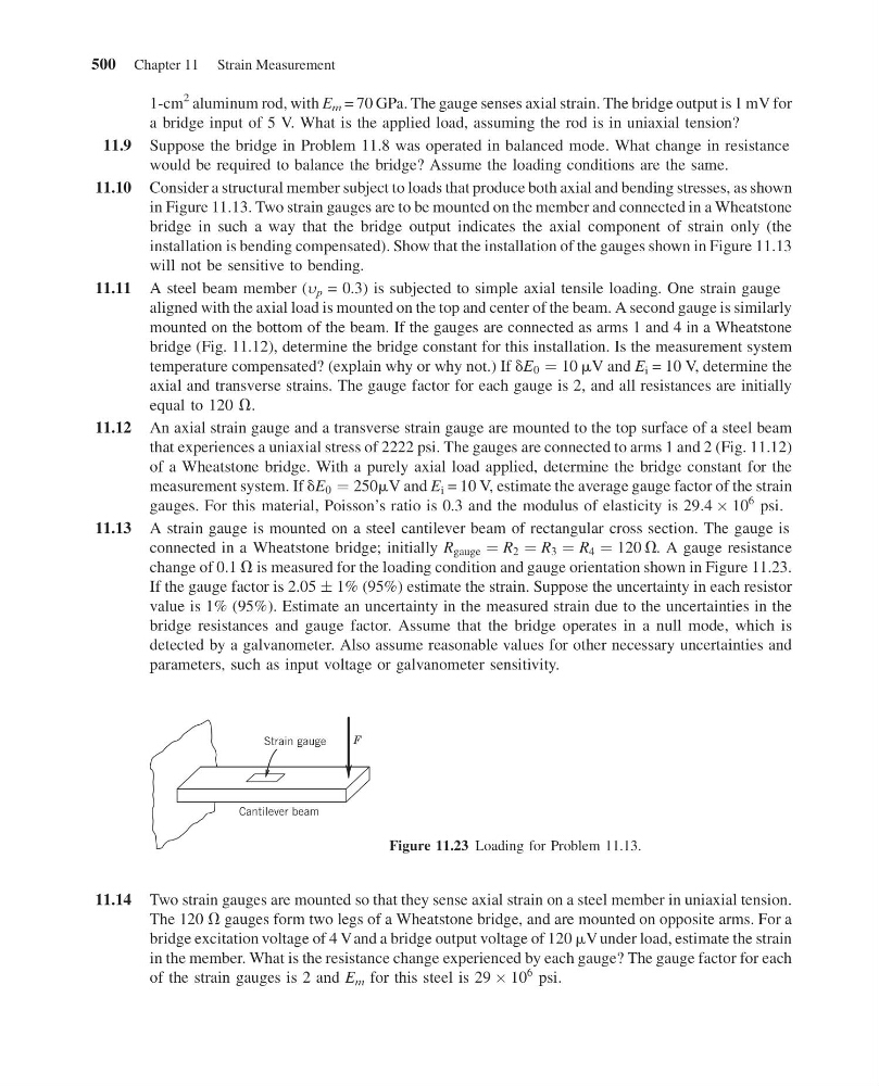
11.13 A strain gauge is mounted on a steel cantilever beam of rectangular cross section. The gauge is
connected in a Wheatstone bridge; initially R gauge ¼ R 2 ¼ R 3 ¼ R 4 ¼ 120 V. A gauge resistance
change of 0.1 V is measured for the loading condition and gauge orientation shown in Figure 11.23.
If the gauge factor is 2.05 Æ 1% (95%) estimate the strain. Suppose the uncertainty in each resistor
value is 1% (95%). Estimate an uncertainty in the measured strain due to the uncertainties in the
bridge resistances and gauge factor. Assume that the bridge operates in a null mode, which is
detected by a galvanometer. Also assume reasonable values for other necessary uncertainties and
parameters, such as input voltage or galvanometer sensitivity.
11.14 Two strain gauges are mounted so that they sense axial strain on a steel member in uniaxial tension.
The 120 V gauges form two legs of a Wheatstone bridge, and are mounted on opposite arms. For a
bridge excitation voltage of 4 Vand a bridge output voltage of 120 mV under load, estimate the strain
in the member. What is the resistance change experienced by each gauge? The gauge factor for each
of the strain gauges is 2 and E m for this steel is 29 Â 10
6 psi.
Strain gauge
F
Cantilever beam
Figure 11.23 Loading for Problem 11.13.
500 Chapter 11 Strain Measurement
13:14:7 Page 500
1-cm
2 aluminum rod, with E m = 70 GPa. The gauge senses axial strain. The bridge output is 1 mV for
a bridge input of 5 V. What is the applied load, assuming the rod is in uniaxial tension?
11.9 Suppose the bridge in Problem 11.8 was operated in balanced mode. What change in resistance
would be required to balance the bridge? Assume the loading conditions are the same.
11.10 Consider a structural member subject to loads that produce both axial and bending stresses, as shown
in Figure 11.13. Two strain gauges are to be mounted on the member and connected in a Wheatstone
bridge in such a way that the bridge output indicates the axial component of strain only (the
installation is bending compensated). Show that the installation of the gauges shown in Figure 11.13
will not be sensitive to bending.
11.11 A steel beam member (y p = 0.3) is subjected to simple axial tensile loading. One strain gauge
aligned with the axial load is mounted on the top and center of the beam. A second gauge is similarly
mounted on the bottom of the beam. If the gauges are connected as arms 1 and 4 in a Wheatstone
bridge (Fig. 11.12), determine the bridge constant for this installation. Is the measurement system
temperature compensated? (explain why or why not.) If dE 0 ¼ 10 mV and E i = 10 V, determine the
axial and transverse strains. The gauge factor for each gauge is 2, and all resistances are initially
equal to 120 V.
11.12 An axial strain gauge and a transverse strain gauge are mounted to the top surface of a steel beam
that experiences a uniaxial stress of 2222 psi. The gauges are connected to arms 1 and 2 (Fig. 11.12)
of a Wheatstone bridge. With a purely axial load applied, determine the bridge constant for the
measurement system. If dE 0 ¼ 250mV and E i = 10 V, estimate the average gauge factor of the strain
gauges. For this material, Poisson’s ratio is 0.3 and the modulus of elasticity is 29:4 Â 10
6 psi.
11.13 A strain gauge is mounted on a steel cantilever beam of rectangular cross section. The gauge is
connected in a Wheatstone bridge; initially R gauge ¼ R 2 ¼ R 3 ¼ R 4 ¼ 120 V. A gauge resistance
change of 0.1 V is measured for the loading condition and gauge orientation shown in Figure 11.23.
If the gauge factor is 2.05 Æ 1% (95%) estimate the strain. Suppose the uncertainty in each resistor
value is 1% (95%). Estimate an uncertainty in the measured strain due to the uncertainties in the
bridge resistances and gauge factor. Assume that the bridge operates in a null mode, which is
detected by a galvanometer. Also assume reasonable values for other necessary uncertainties and
parameters, such as input voltage or galvanometer sensitivity.
11.14 Two strain gauges are mounted so that they sense axial strain on a steel member in uniaxial tension.
The 120 V gauges form two legs of a Wheatstone bridge, and are mounted on opposite arms. For a
bridge excitation voltage of 4 Vand a bridge output voltage of 120 mV under load, estimate the strain
in the member. What is the resistance change experienced by each gauge? The gauge factor for each
of the strain gauges is 2 and E m for this steel is 29 Â 10
6 psi.
Strain gauge
F
Cantilever beam
Figure 11.23 Loading for Problem 11.13.
500 Chapter 11 Strain Measurement