

E1C11 09/14/2010
13:14:5 Page 497
the loci of points where the projected displacements of the surface are integer multiples of the pitch.
The technique then is two-dimensional, providing information concerning the projection of the
displacements into the plane of the master grating. Once a fringe pattern is recorded, data reduction
techniques are employed to determine the stress and strain field. Graphical techniques exist that allow
the strain components in two orthogonal directions to be determined. Further information on moir e
techniques, and additional references may be found in the review article by Sciammarella (13).
Recently, techniques such as moir e-fringe multiplication have greatly increased the sensitivity
of moir e techniques, with possible grating density of 1200 lines/mm. Moir e interferometry is an
extension of moir e-fringe multiplication that uses coherent light and has sensitivities on the order of
0.5 mm/fringe (14). A reflective grating is applied to the specimen, which experiences deformation
under load conditions. The technique provides whole field readings of in-plane strain, with a fourbeam optical arrangement currently in use (15).
11.8 SUMMARY
Experimental stress analysis can be accomplished through several practical techniques, including
electrical resistance, photoelastic, and moir e strain measurement techniques. Each of these methods
yields information concerning the surface strains for a test specimen. The design and selection of an
appropriate strain measurement system begins with the choice of a measurement technique.
The bonded electrical resistance strain gauge provides a versatile means of measuring strain at a
specific location on a test specimen. Strain gauge selection involves the specification of strain gauge
material, the backing or carrier material, and the adhesive used to bond the strain gauge to the test
specimen, as well as the total electrical resistance of the gauge. Other considerations include the
orientation and pattern for a strain gauge rosette, and the temperature limit and maximum allowable
elongation.Inaddition,forelectrical resistancestraingauges, appropriatearrangementofthegaugesina
bridge circuit can provide temperature compensation and elimination of specific components of strain.
Optical methods are useful in the initial determination of a stress field for complex geometries,
and the determination of whole-field information in model studies. Such whole-field methods
provide the basis for design, and establish information necessary to make detailed local strain
measurements.
The techniques for strain measurement described in this chapter provide the basis for
determining surface strains for a test specimen. While the focus here has been the measurement
t
p
t
p
=
= 0.5
for this grating
t
p
= = 0.75
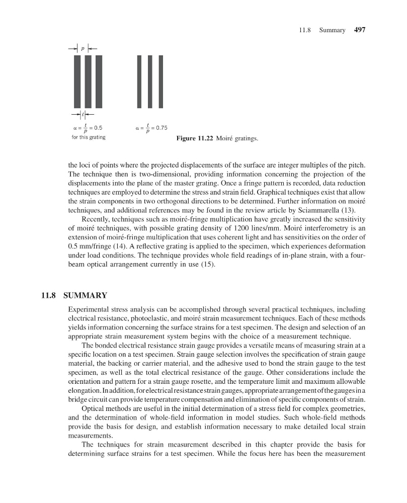
Figure 11.22 Moir e gratings.
11.8 Summary 497
13:14:5 Page 497
the loci of points where the projected displacements of the surface are integer multiples of the pitch.
The technique then is two-dimensional, providing information concerning the projection of the
displacements into the plane of the master grating. Once a fringe pattern is recorded, data reduction
techniques are employed to determine the stress and strain field. Graphical techniques exist that allow
the strain components in two orthogonal directions to be determined. Further information on moir e
techniques, and additional references may be found in the review article by Sciammarella (13).
Recently, techniques such as moir e-fringe multiplication have greatly increased the sensitivity
of moir e techniques, with possible grating density of 1200 lines/mm. Moir e interferometry is an
extension of moir e-fringe multiplication that uses coherent light and has sensitivities on the order of
0.5 mm/fringe (14). A reflective grating is applied to the specimen, which experiences deformation
under load conditions. The technique provides whole field readings of in-plane strain, with a fourbeam optical arrangement currently in use (15).
11.8 SUMMARY
Experimental stress analysis can be accomplished through several practical techniques, including
electrical resistance, photoelastic, and moir e strain measurement techniques. Each of these methods
yields information concerning the surface strains for a test specimen. The design and selection of an
appropriate strain measurement system begins with the choice of a measurement technique.
The bonded electrical resistance strain gauge provides a versatile means of measuring strain at a
specific location on a test specimen. Strain gauge selection involves the specification of strain gauge
material, the backing or carrier material, and the adhesive used to bond the strain gauge to the test
specimen, as well as the total electrical resistance of the gauge. Other considerations include the
orientation and pattern for a strain gauge rosette, and the temperature limit and maximum allowable
elongation.Inaddition,forelectrical resistancestraingauges, appropriatearrangementofthegaugesina
bridge circuit can provide temperature compensation and elimination of specific components of strain.
Optical methods are useful in the initial determination of a stress field for complex geometries,
and the determination of whole-field information in model studies. Such whole-field methods
provide the basis for design, and establish information necessary to make detailed local strain
measurements.
The techniques for strain measurement described in this chapter provide the basis for
determining surface strains for a test specimen. While the focus here has been the measurement
t
p
t
p
=
= 0.5
for this grating
t
p
= = 0.75
Figure 11.22 Moir e gratings.
11.8 Summary 497