

E1C11 09/14/2010
13:14:4 Page 494
stress–optic law:
d / n x À n y
ð11:42Þ
where
d ¼ relative retardation between the two light beams
n x ; n y ¼ indices of refraction in the directions of the principal strains
The index of refraction changes in direct proportion to the amount the material is strained,
such that
n x À n y ¼ K e x À e y
À
Á
ð11:43Þ
The strain optical coefficient, K, is generally assumed to be a material property that is
independent of the wavelength of the incident light. However, if the photoelastic material is
strained beyond the elastic limit, this constant may become wavelength dependent, a phenomenon
known as photoelastic dispersion.
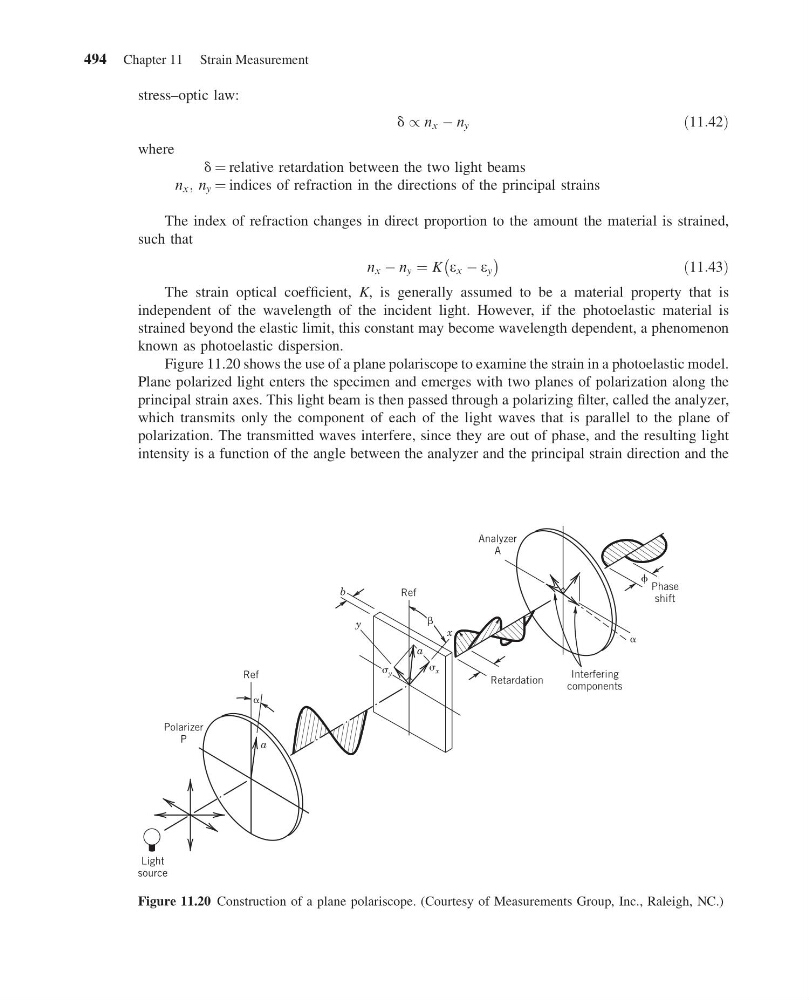
Figure 11.20 shows the use of a plane polariscope to examine the strain in a photoelastic model.
Plane polarized light enters the specimen and emerges with two planes of polarization along the
principal strain axes. This light beam is then passed through a polarizing filter, called the analyzer,
which transmits only the component of each of the light waves that is parallel to the plane of
polarization. The transmitted waves interfere, since they are out of phase, and the resulting light
intensity is a function of the angle between the analyzer and the principal strain direction and the
Polarizer
P
Ref
b
x
y
x
Ref
Retardation
a
Light
source
Interfering
components
Analyzer
A
Phase
shift
y
a
Figure 11.20 Construction of a plane polariscope. (Courtesy of Measurements Group, Inc., Raleigh, NC.)
494 Chapter 11 Strain Measurement
13:14:4 Page 494
stress–optic law:
d / n x À n y
ð11:42Þ
where
d ¼ relative retardation between the two light beams
n x ; n y ¼ indices of refraction in the directions of the principal strains
The index of refraction changes in direct proportion to the amount the material is strained,
such that
n x À n y ¼ K e x À e y
À
Á
ð11:43Þ
The strain optical coefficient, K, is generally assumed to be a material property that is
independent of the wavelength of the incident light. However, if the photoelastic material is
strained beyond the elastic limit, this constant may become wavelength dependent, a phenomenon
known as photoelastic dispersion.
Figure 11.20 shows the use of a plane polariscope to examine the strain in a photoelastic model.
Plane polarized light enters the specimen and emerges with two planes of polarization along the
principal strain axes. This light beam is then passed through a polarizing filter, called the analyzer,
which transmits only the component of each of the light waves that is parallel to the plane of
polarization. The transmitted waves interfere, since they are out of phase, and the resulting light
intensity is a function of the angle between the analyzer and the principal strain direction and the
Polarizer
P
Ref
b
x
y
x
Ref
Retardation
a
Light
source
Interfering
components
Analyzer
A
Phase
shift
y
a
Figure 11.20 Construction of a plane polariscope. (Courtesy of Measurements Group, Inc., Raleigh, NC.)
494 Chapter 11 Strain Measurement