

E1C11 09/14/2010
13:14:4 Page 493
Photoelastic Measurement
Photoelastic methods of stress analysis take advantage of the anisotropic optical characteristics of
some materials, notably plastics, when subject to an applied load to determine the strain field. Stress
analysis may be accomplished either by constructing a model of the part to be analyzed from a material
selected for its optical properties, or by coating the actual part or prototype with a photoelastic coating.
If a model is constructed from a suitable plastic, the required loads for the model are significantly less
than the service loads of the actual part, which reduces effort and expense in testing.
The changes in optical properties, known as artificial birefringence, which occur in certain
materials subject to a load or loads was first observed by Sir David Brewster (10) in 1815. He observed
that when light passes through glass that is subject to uniaxial tension, such that the stress is
perpendicular to the direction of propagation of the light, the glass becomes doubly refracting, with the
axes of polarization in the glass aligned with and perpendicular to the stress. Maxwell (11) and
Neumann (12) first put forward the mathematical observation that the relationship between artificial
birefringence and applied stress or strain is linear. These relations are known as the stress–optic law.
The anisotropy that occurs in photoelastic materials results in two refracted beams of light and
one reflected beam, produced for a single incident beam of appropriately polarized light. The two
refracted beams propagate at different velocities through the material because of an anisotropy in the
index of refraction. In an appropriately designed photoelastic (two-dimensional) model, these two
refracted components of the incident light travel in the same direction and can be examined in a
polariscope. The degree to which the two light waves are out of phase is related to the stress by the
Random emissions
waves and vibrations
contained in various
planes
Wave transmitted
by the polarizer
Wave incident
on the polarizer
P
Polarizer
Light
source
Wave not
transmitted
Transmitted wave vibration
in the plane of P
Vibration transmitted
by the analyzer
Extinction
Analyzer
A
Amplitude
Wave length
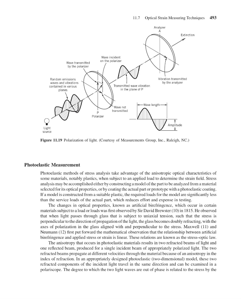
Figure 11.19 Polarization of light. (Courtesy of Measurements Group, Inc., Raleigh, NC.)
11.7 Optical Strain Measuring Techniques 493
13:14:4 Page 493
Photoelastic Measurement
Photoelastic methods of stress analysis take advantage of the anisotropic optical characteristics of
some materials, notably plastics, when subject to an applied load to determine the strain field. Stress
analysis may be accomplished either by constructing a model of the part to be analyzed from a material
selected for its optical properties, or by coating the actual part or prototype with a photoelastic coating.
If a model is constructed from a suitable plastic, the required loads for the model are significantly less
than the service loads of the actual part, which reduces effort and expense in testing.
The changes in optical properties, known as artificial birefringence, which occur in certain
materials subject to a load or loads was first observed by Sir David Brewster (10) in 1815. He observed
that when light passes through glass that is subject to uniaxial tension, such that the stress is
perpendicular to the direction of propagation of the light, the glass becomes doubly refracting, with the
axes of polarization in the glass aligned with and perpendicular to the stress. Maxwell (11) and
Neumann (12) first put forward the mathematical observation that the relationship between artificial
birefringence and applied stress or strain is linear. These relations are known as the stress–optic law.
The anisotropy that occurs in photoelastic materials results in two refracted beams of light and
one reflected beam, produced for a single incident beam of appropriately polarized light. The two
refracted beams propagate at different velocities through the material because of an anisotropy in the
index of refraction. In an appropriately designed photoelastic (two-dimensional) model, these two
refracted components of the incident light travel in the same direction and can be examined in a
polariscope. The degree to which the two light waves are out of phase is related to the stress by the
Random emissions
waves and vibrations
contained in various
planes
Wave transmitted
by the polarizer
Wave incident
on the polarizer
P
Polarizer
Light
source
Wave not
transmitted
Transmitted wave vibration
in the plane of P
Vibration transmitted
by the analyzer
Extinction
Analyzer
A
Amplitude
Wave length
Figure 11.19 Polarization of light. (Courtesy of Measurements Group, Inc., Raleigh, NC.)
11.7 Optical Strain Measuring Techniques 493