

E1C11 09/14/2010
13:14:3 Page 479
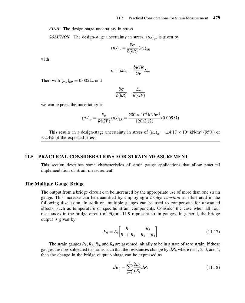
FIND The design-stage uncertainty in stress
SOLUTION The design-stage uncertainty in stress, u d
ð Þ s , is given by
u d
ð Þ s ¼
qs
q dR
ð Þ
u d
ð Þ dR
with
s ¼ eE m ¼
dR=R
GF
E m
Then with u d
ð Þ dR ¼ 0:005 V and
qs
q dR
ð Þ
¼
E m
R GF
ð Þ
we can express the uncertainty as
u d
ð Þ s ¼
E m
R GF
ð Þ
u d
ð Þ dR ¼
200 Â 10
6 kN/m
2
120 V 2
ð Þ
0:005 V
ð
Þ
This results in a design-stage uncertainty in stress of u d
ð Þ s ¼ Æ4:17 Â 10
3 kN/m
2 (95%) or
$2.4% of the expected stress.
11.5 PRACTICAL CONSIDERATIONS FOR STRAIN MEASUREMENT
This section describes some characteristics of strain gauge applications that allow practical
implementation of strain measurement.
The Multiple Gauge Bridge
The output from a bridge circuit can be increased by the appropriate use of more than one strain
gauge. This increase can be quantified by employing a bridge constant as illustrated in the
following discussion. In addition, multiple gauges can be used to compensate for unwanted
effects, such as temperature or specific strain components. Consider the case when all four
resistances in the bridge circuit of Figure 11.9 represent strain gauges. In general, the bridge
output is given by
E 0 ¼ E i
R 1
R 1 þ R 2
À
R 3
R 3 þ R 4
!
ð11:17Þ
The strain gauges R 1 , R 2 , R 3 , and R 4 are assumed initially to be in a state of zero strain. If these
gauges are now subjected to strains such that the resistances change by dR i , where i = 1, 2, 3, and 4,
then the change in the bridge output voltage can be expressed as
dE 0 ¼
X 4
i¼1
qE 0
qR i
dR i
ð11:18Þ
11.5 Practical Considerations for Strain Measurement 479
13:14:3 Page 479
FIND The design-stage uncertainty in stress
SOLUTION The design-stage uncertainty in stress, u d
ð Þ s , is given by
u d
ð Þ s ¼
qs
q dR
ð Þ
u d
ð Þ dR
with
s ¼ eE m ¼
dR=R
GF
E m
Then with u d
ð Þ dR ¼ 0:005 V and
qs
q dR
ð Þ
¼
E m
R GF
ð Þ
we can express the uncertainty as
u d
ð Þ s ¼
E m
R GF
ð Þ
u d
ð Þ dR ¼
200 Â 10
6 kN/m
2
120 V 2
ð Þ
0:005 V
ð
Þ
This results in a design-stage uncertainty in stress of u d
ð Þ s ¼ Æ4:17 Â 10
3 kN/m
2 (95%) or
$2.4% of the expected stress.
11.5 PRACTICAL CONSIDERATIONS FOR STRAIN MEASUREMENT
This section describes some characteristics of strain gauge applications that allow practical
implementation of strain measurement.
The Multiple Gauge Bridge
The output from a bridge circuit can be increased by the appropriate use of more than one strain
gauge. This increase can be quantified by employing a bridge constant as illustrated in the
following discussion. In addition, multiple gauges can be used to compensate for unwanted
effects, such as temperature or specific strain components. Consider the case when all four
resistances in the bridge circuit of Figure 11.9 represent strain gauges. In general, the bridge
output is given by
E 0 ¼ E i
R 1
R 1 þ R 2
À
R 3
R 3 þ R 4
!
ð11:17Þ
The strain gauges R 1 , R 2 , R 3 , and R 4 are assumed initially to be in a state of zero strain. If these
gauges are now subjected to strains such that the resistances change by dR i , where i = 1, 2, 3, and 4,
then the change in the bridge output voltage can be expressed as
dE 0 ¼
X 4
i¼1
qE 0
qR i
dR i
ð11:18Þ
11.5 Practical Considerations for Strain Measurement 479