

E1C11 09/14/2010
13:14:1 Page 467
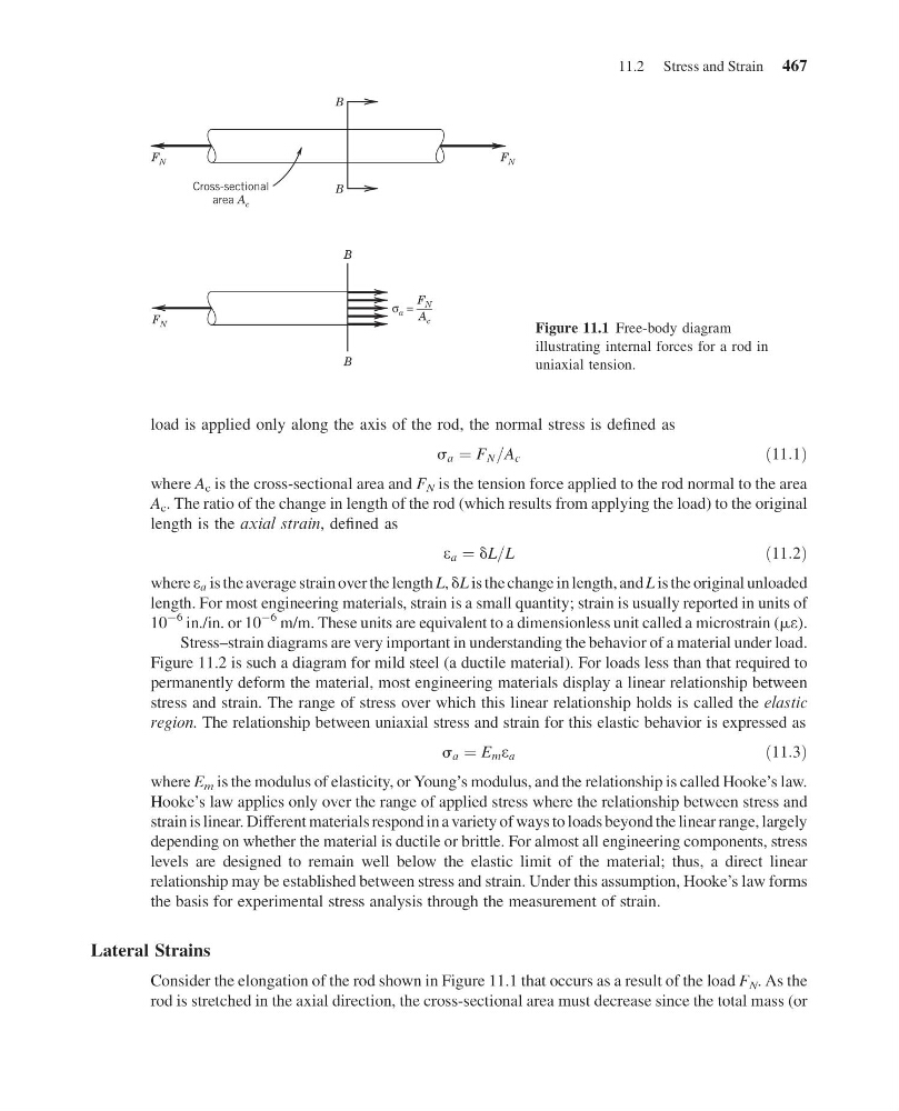
load is applied only along the axis of the rod, the normal stress is defined as
s a ¼ F N =A c
ð11:1Þ
where A c is the cross-sectional area and F N is the tension force applied to the rod normal to the area
A c . The ratio of the change in length of the rod (which results from applying the load) to the original
length is the axial strain, defined as
e a ¼ dL=L
ð11:2Þ
where e a is the average strain over the length L, dL is the change in length, and L is the original unloaded
length. For most engineering materials, strain is a small quantity; strain is usually reported in units of
10
À6 in./in. or 10
À6 m/m. These units are equivalent to a dimensionless unit called a microstrain (me).
Stress–strain diagrams are very important in understanding the behavior of a material under load.
Figure 11.2 is such a diagram for mild steel (a ductile material). For loads less than that required to
permanently deform the material, most engineering materials display a linear relationship between
stress and strain. The range of stress over which this linear relationship holds is called the elastic
region. The relationship between uniaxial stress and strain for this elastic behavior is expressed as
s a ¼ E m e a
ð11:3Þ
where E m is the modulus of elasticity, or Young’s modulus, and the relationship is called Hooke’s law.
Hooke’s law applies only over the range of applied stress where the relationship between stress and
strain is linear. Different materials respond in a variety of ways to loads beyond the linear range, largely
depending on whether the material is ductile or brittle. For almost all engineering components, stress
levels are designed to remain well below the elastic limit of the material; thus, a direct linear
relationship may be established between stress and strain. Under this assumption, Hooke’s law forms
the basis for experimental stress analysis through the measurement of strain.
Lateral Strains
Consider the elongation of the rod shown in Figure 11.1 that occurs as a result of the load F N . As the
rod is stretched in the axial direction, the cross-sectional area must decrease since the total mass (or
F N
F N
F N
B
B
B
B
F N
A c
σ a =
Cross-sectional
area A c
Figure 11.1 Free-body diagram
illustrating internal forces for a rod in
uniaxial tension.
11.2 Stress and Strain 467
13:14:1 Page 467
load is applied only along the axis of the rod, the normal stress is defined as
s a ¼ F N =A c
ð11:1Þ
where A c is the cross-sectional area and F N is the tension force applied to the rod normal to the area
A c . The ratio of the change in length of the rod (which results from applying the load) to the original
length is the axial strain, defined as
e a ¼ dL=L
ð11:2Þ
where e a is the average strain over the length L, dL is the change in length, and L is the original unloaded
length. For most engineering materials, strain is a small quantity; strain is usually reported in units of
10
À6 in./in. or 10
À6 m/m. These units are equivalent to a dimensionless unit called a microstrain (me).
Stress–strain diagrams are very important in understanding the behavior of a material under load.
Figure 11.2 is such a diagram for mild steel (a ductile material). For loads less than that required to
permanently deform the material, most engineering materials display a linear relationship between
stress and strain. The range of stress over which this linear relationship holds is called the elastic
region. The relationship between uniaxial stress and strain for this elastic behavior is expressed as
s a ¼ E m e a
ð11:3Þ
where E m is the modulus of elasticity, or Young’s modulus, and the relationship is called Hooke’s law.
Hooke’s law applies only over the range of applied stress where the relationship between stress and
strain is linear. Different materials respond in a variety of ways to loads beyond the linear range, largely
depending on whether the material is ductile or brittle. For almost all engineering components, stress
levels are designed to remain well below the elastic limit of the material; thus, a direct linear
relationship may be established between stress and strain. Under this assumption, Hooke’s law forms
the basis for experimental stress analysis through the measurement of strain.
Lateral Strains
Consider the elongation of the rod shown in Figure 11.1 that occurs as a result of the load F N . As the
rod is stretched in the axial direction, the cross-sectional area must decrease since the total mass (or
F N
F N
F N
B
B
B
B
F N
A c
σ a =
Cross-sectional
area A c
Figure 11.1 Free-body diagram
illustrating internal forces for a rod in
uniaxial tension.
11.2 Stress and Strain 467