

E1C10 09/14/2010
13:4:48 Page 462
NOMENCLATURE
c p , c v
specific heats (l
2 /t
2 -
)
d
diameter (l )
d 0
flow meter throat or minimum
diameter (l )
d 1
pipe diameter (l )
d 2
vena contracta diameter (see
Fig. 10.3) (l )
f
cyclical frequency (v/2p) (t
À1 )
g
gravitational acceleration constant
(lt
À2 )
h L 1À2
energy head loss between points 1 and
2 (l )
k
ratio of specific heats, c p /c v
C
discharge coefficient
C D
drag coefficient
E
velocity of approach factor; voltage
Gr
Grashof number
H
manometer deflection (l )
K 0
flow coefficient (¼ CE)
K 1
flow meter constant; K-factor; static
sensitivity
L
length (l )
Q
volume flow rate (l
3 t
À1 )
R
gas constant
Re d 1
Reynolds number (based on d 1 )
_
m
mass flow rate (mt
À1 )
p
pressure (ml
À1
t
À2 )
p 1 Àp 2 , Dp pressure differential (ml
À1
t
À2 )
Dp loss
permanent pressure loss (ml
À1
t
À2 )
r
radial coordinate (l )
r 1
pipe radius (l )
r H
hydraulic radius (l )
A
area (l
2
)
A 0
area based on d 0 (l
2 )
A 1
area based on pipe diameter d 1 (l
2 )
A 2
vena contracta area (l
2 )
B
magnetic field flux vector
S
specific gravity
T
temperature (
); torque (ml
2
t
À2 )
U
velocity (lt
À1 )
8
volume (l
3 )
Y
expansion factor
b
diameter ratio
r
density (ml
À3
)
d
twist angle
v
frequency (t
À1 ); angular velocity (t
À1 )
m
absolute viscosity (ml
À1
t
À1 )
v
kinematic viscosity (=m/r) (l
2 t
À1 )
PROBLEMS
10.1 Determine the average mass flow rate of 5
C air at 1 bar abs through a 5-cm-i.d. pipe whose velocity
profile is found to be symmetric and described by U r
ð Þ ¼ 25 1 À r=r 1
ð
Þ
2
h
i
cm/s
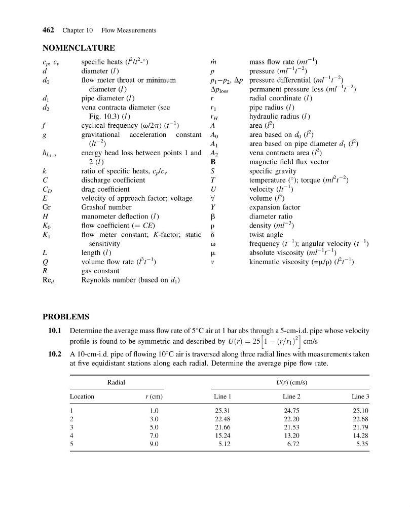
10.2 A 10-cm-i.d. pipe of flowing 10
C air is traversed along three radial lines with measurements taken
at five equidistant stations along each radial. Determine the average pipe flow rate.
Radial
U(r) (cm/s)
Location
r (cm)
Line 1
Line 2
Line 3
1
1.0
25.31
24.75
25.10
2
3.0
22.48
22.20
22.68
3
5.0
21.66
21.53
21.79
4
7.0
15.24
13.20
14.28
5
9.0
5.12
6.72
5.35
462 Chapter 10 Flow Measurements
13:4:48 Page 462
NOMENCLATURE
c p , c v
specific heats (l
2 /t
2 -
)
d
diameter (l )
d 0
flow meter throat or minimum
diameter (l )
d 1
pipe diameter (l )
d 2
vena contracta diameter (see
Fig. 10.3) (l )
f
cyclical frequency (v/2p) (t
À1 )
g
gravitational acceleration constant
(lt
À2 )
h L 1À2
energy head loss between points 1 and
2 (l )
k
ratio of specific heats, c p /c v
C
discharge coefficient
C D
drag coefficient
E
velocity of approach factor; voltage
Gr
Grashof number
H
manometer deflection (l )
K 0
flow coefficient (¼ CE)
K 1
flow meter constant; K-factor; static
sensitivity
L
length (l )
Q
volume flow rate (l
3 t
À1 )
R
gas constant
Re d 1
Reynolds number (based on d 1 )
_
m
mass flow rate (mt
À1 )
p
pressure (ml
À1
t
À2 )
p 1 Àp 2 , Dp pressure differential (ml
À1
t
À2 )
Dp loss
permanent pressure loss (ml
À1
t
À2 )
r
radial coordinate (l )
r 1
pipe radius (l )
r H
hydraulic radius (l )
A
area (l
2
)
A 0
area based on d 0 (l
2 )
A 1
area based on pipe diameter d 1 (l
2 )
A 2
vena contracta area (l
2 )
B
magnetic field flux vector
S
specific gravity
T
temperature (
); torque (ml
2
t
À2 )
U
velocity (lt
À1 )
8
volume (l
3 )
Y
expansion factor
b
diameter ratio
r
density (ml
À3
)
d
twist angle
v
frequency (t
À1 ); angular velocity (t
À1 )
m
absolute viscosity (ml
À1
t
À1 )
v
kinematic viscosity (=m/r) (l
2 t
À1 )
PROBLEMS
10.1 Determine the average mass flow rate of 5
C air at 1 bar abs through a 5-cm-i.d. pipe whose velocity
profile is found to be symmetric and described by U r
ð Þ ¼ 25 1 À r=r 1
ð
Þ
2
h
i
cm/s
10.2 A 10-cm-i.d. pipe of flowing 10
C air is traversed along three radial lines with measurements taken
at five equidistant stations along each radial. Determine the average pipe flow rate.
Radial
U(r) (cm/s)
Location
r (cm)
Line 1
Line 2
Line 3
1
1.0
25.31
24.75
25.10
2
3.0
22.48
22.20
22.68
3
5.0
21.66
21.53
21.79
4
7.0
15.24
13.20
14.28
5
9.0
5.12
6.72
5.35
462 Chapter 10 Flow Measurements