

E1C10 09/14/2010
13:4:39 Page 440
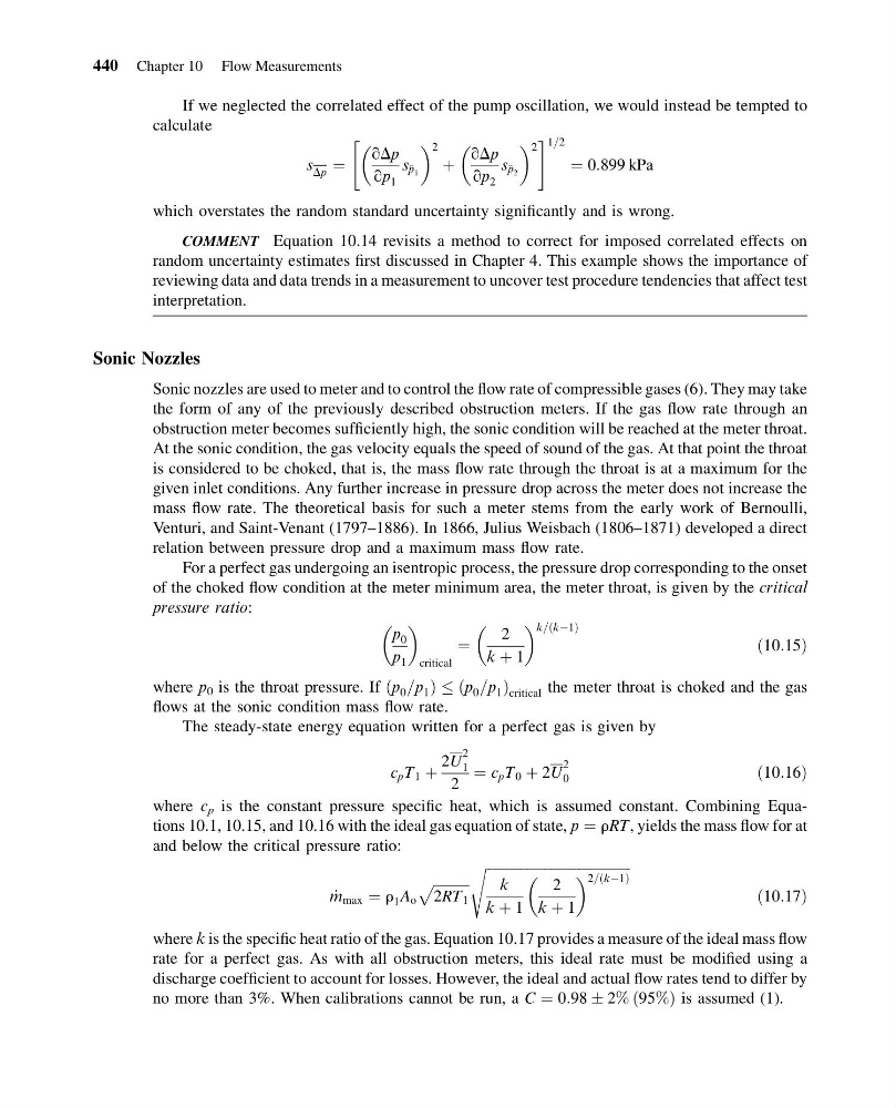
If we neglected the correlated effect of the pump oscillation, we would instead be tempted to
calculate
s Dp ¼
qDp
qp 1
s p 1
2
þ
qDp
qp 2
s p 2
2
"
# 1=2
¼ 0:899 kPa
which overstates the random standard uncertainty significantly and is wrong.
COMMENT Equation 10.14 revisits a method to correct for imposed correlated effects on
random uncertainty estimates first discussed in Chapter 4. This example shows the importance of
reviewing data and data trends in a measurement to uncover test procedure tendencies that affect test
interpretation.
Sonic Nozzles
Sonic nozzles are used to meter and to control the flow rate of compressible gases (6). They may take
the form of any of the previously described obstruction meters. If the gas flow rate through an
obstruction meter becomes sufficiently high, the sonic condition will be reached at the meter throat.
At the sonic condition, the gas velocity equals the speed of sound of the gas. At that point the throat
is considered to be choked, that is, the mass flow rate through the throat is at a maximum for the
given inlet conditions. Any further increase in pressure drop across the meter does not increase the
mass flow rate. The theoretical basis for such a meter stems from the early work of Bernoulli,
Venturi, and Saint-Venant (1797–1886). In 1866, Julius Weisbach (1806–1871) developed a direct
relation between pressure drop and a maximum mass flow rate.
For a perfect gas undergoing an isentropic process, the pressure drop corresponding to the onset
of the choked flow condition at the meter minimum area, the meter throat, is given by the critical
pressure ratio:
p 0
p 1
critical
¼
2
k þ 1
k=ðkÀ1Þ
ð10:15Þ
where p 0 is the throat pressure. If p 0 =p 1
ð
Þ
p 0 =p 1
ð
Þ critical the meter throat is choked and the gas
flows at the sonic condition mass flow rate.
The steady-state energy equation written for a perfect gas is given by
c p T 1 þ
2U
2
1
2
¼ c p T 0 þ 2U
2
0
ð10:16Þ
where c p is the constant pressure specific heat, which is assumed constant. Combining Equations 10.1, 10.15, and 10.16 with the ideal gas equation of state, p ¼ rRT, yields the mass flow for at
and below the critical pressure ratio:
_
m max ¼ r 1 A o
ffiffiffiffiffiffiffiffiffiffi ffi
2RT 1
p
ffiffiffiffiffiffiffiffiffiffiffiffiffiffiffiffiffiffiffiffiffiffiffiffiffiffiffiffiffiffiffiffiffiffiffiffiffiffiffiffiffiffi
k
k þ 1
2
k þ 1
2=ðkÀ1Þ
s
ð10:17Þ
where k is the specific heat ratio of the gas. Equation 10.17 provides a measure of the ideal mass flow
rate for a perfect gas. As with all obstruction meters, this ideal rate must be modified using a
discharge coefficient to account for losses. However, the ideal and actual flow rates tend to differ by
no more than 3%. When calibrations cannot be run, a C ¼ 0:98 Æ 2% ð95%Þ is assumed (1).
440 Chapter 10 Flow Measurements
13:4:39 Page 440
If we neglected the correlated effect of the pump oscillation, we would instead be tempted to
calculate
s Dp ¼
qDp
qp 1
s p 1
2
þ
qDp
qp 2
s p 2
2
"
# 1=2
¼ 0:899 kPa
which overstates the random standard uncertainty significantly and is wrong.
COMMENT Equation 10.14 revisits a method to correct for imposed correlated effects on
random uncertainty estimates first discussed in Chapter 4. This example shows the importance of
reviewing data and data trends in a measurement to uncover test procedure tendencies that affect test
interpretation.
Sonic Nozzles
Sonic nozzles are used to meter and to control the flow rate of compressible gases (6). They may take
the form of any of the previously described obstruction meters. If the gas flow rate through an
obstruction meter becomes sufficiently high, the sonic condition will be reached at the meter throat.
At the sonic condition, the gas velocity equals the speed of sound of the gas. At that point the throat
is considered to be choked, that is, the mass flow rate through the throat is at a maximum for the
given inlet conditions. Any further increase in pressure drop across the meter does not increase the
mass flow rate. The theoretical basis for such a meter stems from the early work of Bernoulli,
Venturi, and Saint-Venant (1797–1886). In 1866, Julius Weisbach (1806–1871) developed a direct
relation between pressure drop and a maximum mass flow rate.
For a perfect gas undergoing an isentropic process, the pressure drop corresponding to the onset
of the choked flow condition at the meter minimum area, the meter throat, is given by the critical
pressure ratio:
p 0
p 1
critical
¼
2
k þ 1
k=ðkÀ1Þ
ð10:15Þ
where p 0 is the throat pressure. If p 0 =p 1
ð
Þ
p 0 =p 1
ð
Þ critical the meter throat is choked and the gas
flows at the sonic condition mass flow rate.
The steady-state energy equation written for a perfect gas is given by
c p T 1 þ
2U
2
1
2
¼ c p T 0 þ 2U
2
0
ð10:16Þ
where c p is the constant pressure specific heat, which is assumed constant. Combining Equations 10.1, 10.15, and 10.16 with the ideal gas equation of state, p ¼ rRT, yields the mass flow for at
and below the critical pressure ratio:
_
m max ¼ r 1 A o
ffiffiffiffiffiffiffiffiffiffi ffi
2RT 1
p
ffiffiffiffiffiffiffiffiffiffiffiffiffiffiffiffiffiffiffiffiffiffiffiffiffiffiffiffiffiffiffiffiffiffiffiffiffiffiffiffiffiffi
k
k þ 1
2
k þ 1
2=ðkÀ1Þ
s
ð10:17Þ
where k is the specific heat ratio of the gas. Equation 10.17 provides a measure of the ideal mass flow
rate for a perfect gas. As with all obstruction meters, this ideal rate must be modified using a
discharge coefficient to account for losses. However, the ideal and actual flow rates tend to differ by
no more than 3%. When calibrations cannot be run, a C ¼ 0:98 Æ 2% ð95%Þ is assumed (1).
440 Chapter 10 Flow Measurements