

E1C10 09/14/2010
13:4:37 Page 425
to achieve necessary accuracy. This can be because the density changes or it may not be well known,
such as in the transport of polymers or petrochemicals, or because small errors in density accumulate
into large errors, such as in the transport of millions of cubic meters of product per day.
The flow character can affect the accuracy of a flow meter. The flow through a pipe or duct can
be characterized as being laminar, turbulent, or a transition between the two. Flow character is
determined through the nondimensional parameter known as the Reynolds number, defined by
Re d 1 ¼
Ud 1
v
¼
4Q
pd 1 v
ð10:3Þ
where v is the fluid kinematic viscosity and d 1 is the diameter for circular pipes. In pipes, the flow is
laminar when Re d 1 < 2000 and turbulent at higher Reynolds number. The Reynolds number is a
necessary parameter in estimating flow rate when using several of the types of flow meters discussed. In
estimating the Reynolds number in noncircular conduits, the hydraulic diameter, 4r H , is used in place
of diameter d 1 , where r H is the wetted conduit area divided by its wetted perimeter.
10.4 VOLUME FLOW RATE THROUGH VELOCITY DETERMINATION
Volume flow rate can be determined with direct knowledge of the velocity profile as indicated by
Equation 10.2. This requires measuring the velocity at multiple points along a cross section of a
conduit to estimate the velocity profile. For highest accuracy, several traverses should be made at
differing circumferential locations to account for flow nonsymmetry. Methods for determining the
velocity at a point include any of those previously discussed in Chapter 9. Because it is a tedious
method, this procedure is most often used for the one-time verification or calibration of system flow
rates. For example, the procedure is often used in ventilation system setup and problem diagnosis,
where the installation of an in-line flow meter is not necessary because operation does not require
continuous monitoring.
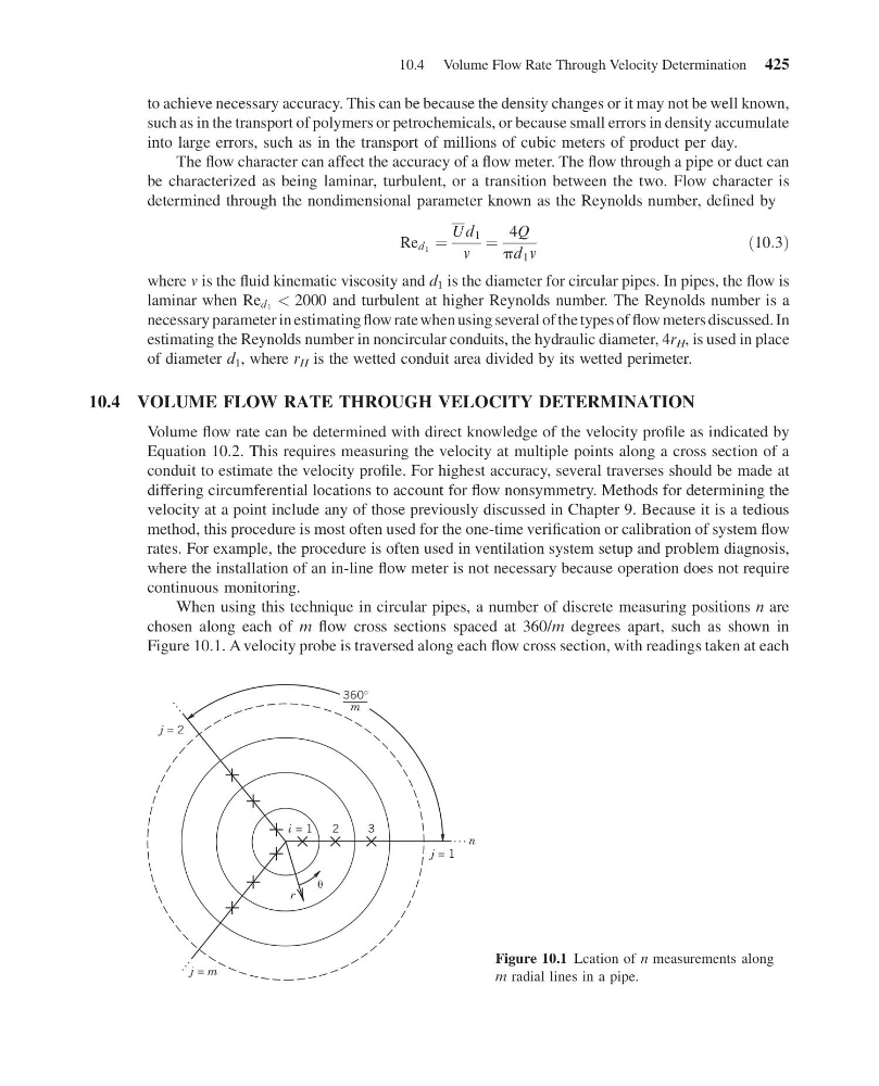
When using this technique in circular pipes, a number of discrete measuring positions n are
chosen along each of m flow cross sections spaced at 360/m degrees apart, such as shown in
Figure 10.1. A velocity probe is traversed along each flow cross section, with readings taken at each
j = 2
j = m
j = 1
. . .
.
.
.
.
.
.
i = 1
2
r
3
n
360°
m
Figure 10.1 Lcation of n measurements along
m radial lines in a pipe.
10.4 Volume Flow Rate Through Velocity Determination 425
13:4:37 Page 425
to achieve necessary accuracy. This can be because the density changes or it may not be well known,
such as in the transport of polymers or petrochemicals, or because small errors in density accumulate
into large errors, such as in the transport of millions of cubic meters of product per day.
The flow character can affect the accuracy of a flow meter. The flow through a pipe or duct can
be characterized as being laminar, turbulent, or a transition between the two. Flow character is
determined through the nondimensional parameter known as the Reynolds number, defined by
Re d 1 ¼
Ud 1
v
¼
4Q
pd 1 v
ð10:3Þ
where v is the fluid kinematic viscosity and d 1 is the diameter for circular pipes. In pipes, the flow is
laminar when Re d 1 < 2000 and turbulent at higher Reynolds number. The Reynolds number is a
necessary parameter in estimating flow rate when using several of the types of flow meters discussed. In
estimating the Reynolds number in noncircular conduits, the hydraulic diameter, 4r H , is used in place
of diameter d 1 , where r H is the wetted conduit area divided by its wetted perimeter.
10.4 VOLUME FLOW RATE THROUGH VELOCITY DETERMINATION
Volume flow rate can be determined with direct knowledge of the velocity profile as indicated by
Equation 10.2. This requires measuring the velocity at multiple points along a cross section of a
conduit to estimate the velocity profile. For highest accuracy, several traverses should be made at
differing circumferential locations to account for flow nonsymmetry. Methods for determining the
velocity at a point include any of those previously discussed in Chapter 9. Because it is a tedious
method, this procedure is most often used for the one-time verification or calibration of system flow
rates. For example, the procedure is often used in ventilation system setup and problem diagnosis,
where the installation of an in-line flow meter is not necessary because operation does not require
continuous monitoring.
When using this technique in circular pipes, a number of discrete measuring positions n are
chosen along each of m flow cross sections spaced at 360/m degrees apart, such as shown in
Figure 10.1. A velocity probe is traversed along each flow cross section, with readings taken at each
j = 2
j = m
j = 1
. . .
.
.
.
.
.
.
i = 1
2
r
3
n
360°
m
Figure 10.1 Lcation of n measurements along
m radial lines in a pipe.
10.4 Volume Flow Rate Through Velocity Determination 425