

E1C09 09/14/2010
15:4:55 Page 408
Thermal Anemometry
The rate at which energy, _
Q, is transferred between a warm body at T s and a cooler moving fluid at T f
is proportional both to the temperature difference between them and to the thermal conductance of
the heat transfer path, hA. This thermal conductance increases with fluid velocity, thereby increasing
the rate of heat transfer at any given temperature difference. Hence, a relationship between the rate
of heat transfer and velocity exists forming the working basis of a thermal anemometer.
A thermal anemometer utilizes a sensor, a metallic resistance temperature detector (RTD)
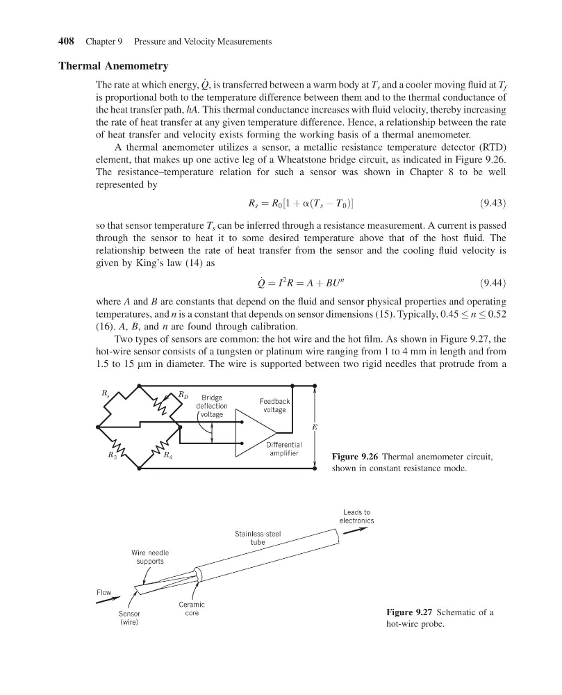
element, that makes up one active leg of a Wheatstone bridge circuit, as indicated in Figure 9.26.
The resistance–temperature relation for such a sensor was shown in Chapter 8 to be well
represented by
R s ¼ R 0 1 þ a T s À T 0
ð
Þ
½
ð 9:43Þ
so that sensor temperature T s can be inferred through a resistance measurement. A current is passed
through the sensor to heat it to some desired temperature above that of the host fluid. The
relationship between the rate of heat transfer from the sensor and the cooling fluid velocity is
given by King’s law (14) as
_
Q ¼ I
2
R ¼ A þ BU
n
ð9:44Þ
where A and B are constants that depend on the fluid and sensor physical properties and operating
temperatures, and n is a constant that depends on sensor dimensions (15). Typically, 0.45 n 0.52
(16). A, B, and n are found through calibration.
Two types of sensors are common: the hot wire and the hot film. As shown in Figure 9.27, the
hot-wire sensor consists of a tungsten or platinum wire ranging from 1 to 4 mm in length and from
1.5 to 15 mm in diameter. The wire is supported between two rigid needles that protrude from a
R 3
R 4
R D
R s
Bridge
deflection
voltage
Differential
amplifier
Feedback
voltage
E
Figure 9.26 Thermal anemometer circuit,
shown in constant resistance mode.
Leads to
electronics
Stainless-steel
tube
Wire needle
supports
Sensor
(wire)
Flow
Ceramic
core
Figure 9.27 Schematic of a
hot-wire probe.
408 Chapter 9 Pressure and Velocity Measurements
15:4:55 Page 408
Thermal Anemometry
The rate at which energy, _
Q, is transferred between a warm body at T s and a cooler moving fluid at T f
is proportional both to the temperature difference between them and to the thermal conductance of
the heat transfer path, hA. This thermal conductance increases with fluid velocity, thereby increasing
the rate of heat transfer at any given temperature difference. Hence, a relationship between the rate
of heat transfer and velocity exists forming the working basis of a thermal anemometer.
A thermal anemometer utilizes a sensor, a metallic resistance temperature detector (RTD)
element, that makes up one active leg of a Wheatstone bridge circuit, as indicated in Figure 9.26.
The resistance–temperature relation for such a sensor was shown in Chapter 8 to be well
represented by
R s ¼ R 0 1 þ a T s À T 0
ð
Þ
½
ð 9:43Þ
so that sensor temperature T s can be inferred through a resistance measurement. A current is passed
through the sensor to heat it to some desired temperature above that of the host fluid. The
relationship between the rate of heat transfer from the sensor and the cooling fluid velocity is
given by King’s law (14) as
_
Q ¼ I
2
R ¼ A þ BU
n
ð9:44Þ
where A and B are constants that depend on the fluid and sensor physical properties and operating
temperatures, and n is a constant that depends on sensor dimensions (15). Typically, 0.45 n 0.52
(16). A, B, and n are found through calibration.
Two types of sensors are common: the hot wire and the hot film. As shown in Figure 9.27, the
hot-wire sensor consists of a tungsten or platinum wire ranging from 1 to 4 mm in length and from
1.5 to 15 mm in diameter. The wire is supported between two rigid needles that protrude from a
R 3
R 4
R D
R s
Bridge
deflection
voltage
Differential
amplifier
Feedback
voltage
E
Figure 9.26 Thermal anemometer circuit,
shown in constant resistance mode.
Leads to
electronics
Stainless-steel
tube
Wire needle
supports
Sensor
(wire)
Flow
Ceramic
core
Figure 9.27 Schematic of a
hot-wire probe.
408 Chapter 9 Pressure and Velocity Measurements