

E1C09 09/14/2010
15:4:53 Page 381
available, allowing measurements ranging from the order of 0.001 mm of manometer fluid to several
meters.
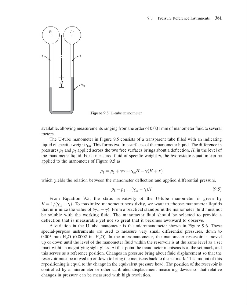
The U-tube manometer in Figure 9.5 consists of a transparent tube filled with an indicating
liquid of specific weight g m . This forms two free surfaces of the manometer liquid. The difference in
pressures p 1 and p 2 applied across the two free surfaces brings about a deflection, H, in the level of
the manometer liquid. For a measured fluid of specific weight g, the hydrostatic equation can be
applied to the manometer of Figure 9.5 as
p 1 ¼ p 2 þ gx þ g m H À gðH þ xÞ
which yields the relation between the manometer deflection and applied differential pressure,
p 1 À p 2 ¼ g m À g
ð
ÞH
ð9:5Þ
From Equation 9.5, the static sensitivity of the U-tube manometer is given by
K ¼ 1=ðg m À gÞ. To maximize manometer sensitivity, we want to choose manometer liquids
that minimize the value of (g m À g). From a practical standpoint the manometer fluid must not
be soluble with the working fluid. The manometer fluid should be selected to provide a
deflection that is measurable yet not so great that it becomes awkward to observe.
A variation in the U-tube manometer is the micromanometer shown in Figure 9.6. These
special-purpose instruments are used to measure very small differential pressures, down to
0.005 mm H 2 O (0.0002 in. H 2 O). In the micromanometer, the manometer reservoir is moved
up or down until the level of the manometer fluid within the reservoir is at the same level as a set
mark within a magnifying sight glass. At that point the manometer meniscus is at the set mark, and
this serves as a reference position. Changes in pressure bring about fluid displacement so that the
reservoir must be moved up or down to bring the meniscus back to the set mark. The amount of this
repositioning is equal to the change in the equivalent pressure head. The position of the reservoir is
controlled by a micrometer or other calibrated displacement measuring device so that relative
changes in pressure can be measured with high resolution.
H
x
p 1
p 2
m
Figure 9.5 U-tube manometer.
9.3 Pressure Reference Instruments 381
15:4:53 Page 381
available, allowing measurements ranging from the order of 0.001 mm of manometer fluid to several
meters.
The U-tube manometer in Figure 9.5 consists of a transparent tube filled with an indicating
liquid of specific weight g m . This forms two free surfaces of the manometer liquid. The difference in
pressures p 1 and p 2 applied across the two free surfaces brings about a deflection, H, in the level of
the manometer liquid. For a measured fluid of specific weight g, the hydrostatic equation can be
applied to the manometer of Figure 9.5 as
p 1 ¼ p 2 þ gx þ g m H À gðH þ xÞ
which yields the relation between the manometer deflection and applied differential pressure,
p 1 À p 2 ¼ g m À g
ð
ÞH
ð9:5Þ
From Equation 9.5, the static sensitivity of the U-tube manometer is given by
K ¼ 1=ðg m À gÞ. To maximize manometer sensitivity, we want to choose manometer liquids
that minimize the value of (g m À g). From a practical standpoint the manometer fluid must not
be soluble with the working fluid. The manometer fluid should be selected to provide a
deflection that is measurable yet not so great that it becomes awkward to observe.
A variation in the U-tube manometer is the micromanometer shown in Figure 9.6. These
special-purpose instruments are used to measure very small differential pressures, down to
0.005 mm H 2 O (0.0002 in. H 2 O). In the micromanometer, the manometer reservoir is moved
up or down until the level of the manometer fluid within the reservoir is at the same level as a set
mark within a magnifying sight glass. At that point the manometer meniscus is at the set mark, and
this serves as a reference position. Changes in pressure bring about fluid displacement so that the
reservoir must be moved up or down to bring the meniscus back to the set mark. The amount of this
repositioning is equal to the change in the equivalent pressure head. The position of the reservoir is
controlled by a micrometer or other calibrated displacement measuring device so that relative
changes in pressure can be measured with high resolution.
H
x
p 1
p 2
m
Figure 9.5 U-tube manometer.
9.3 Pressure Reference Instruments 381