

E1C08 09/14/2010
14:54:2 Page 359
u x
ð Þ
u w
¼
cosh mx
cosh mL
ð8:25Þ
The point x ¼ 0 is the location where the temperature is assumed to be measured, and therefore the
solution is evaluated at x ¼ 0 as
u 0
ð Þ
u w
¼
T 0
ð Þ À T 1
T w À T 1
¼
1
cosh mL
ð8:26Þ
From this analysis, the error due to conduction, e c , can be estimated. An ideal sensor would indicate
the fluid temperature T 1 ; therefore, if the sensor temperature is T p ¼ T 0
ð Þ, then the conduction
error is
e c ¼ T p À T 1 ¼
T w À T 1
cosh mL
ð8:27Þ
Normally, the uncertainty due to conduction error is set at u ¼ e c . The uncertainty interval may not
be symmetric.
Probe Design
The purpose of the preceding analysis is to gain some physical understanding of ways to minimize
conduction errors (not to correct inaccurate measurements). The behavior of this solution is such
that the ideal temperature probe would have T p ¼ T 1 , or u 0
ð Þ ¼ 0, implying that e c ¼ 0. Equation
8.26 shows that a value of u 0
ð Þ 6 ¼ 0 results from a nonzero value of u w , and a finite value of cosh mL.
The difference between the fluid temperature being measured and the wall temperature should be as
small as possible; clearly, this implies that the wall should be insulated to minimize this temperature
difference, and the resulting conduction error.
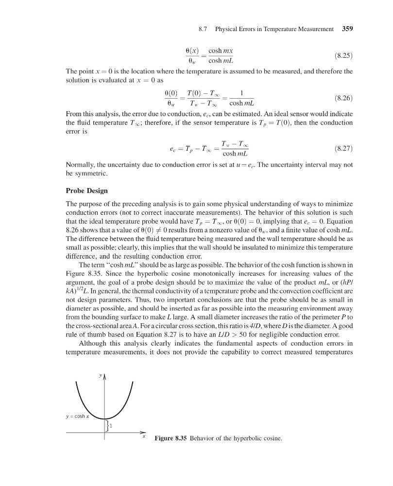
The term ‘‘cosh mL’’ should be as large as possible. The behavior of the cosh function is shown in
Figure 8.35. Since the hyperbolic cosine monotonically increases for increasing values of the
argument, the goal of a probe design should be to maximize the value of the product mL, or (hP/
kA)
1/2
L. In general, the thermal conductivity of a temperature probe and the convection coefficient are
not design parameters. Thus, two important conclusions are that the probe should be as small in
diameter as possible, and should be inserted as far as possible into the measuring environment away
from the bounding surface to make L large. A small diameter increases the ratio of the perimeter P to
the cross-sectional area A. For a circular cross section, this ratio is 4/D, where D is the diameter. A good
rule of thumb based on Equation 8.27 is to have an L/D > 50 for negligible conduction error.
Although this analysis clearly indicates the fundamental aspects of conduction errors in
temperature measurements, it does not provide the capability to correct measured temperatures
x
1
y
y = cosh x
Figure 8.35 Behavior of the hyperbolic cosine.
8.7 Physical Errors in Temperature Measurement 359
14:54:2 Page 359
u x
ð Þ
u w
¼
cosh mx
cosh mL
ð8:25Þ
The point x ¼ 0 is the location where the temperature is assumed to be measured, and therefore the
solution is evaluated at x ¼ 0 as
u 0
ð Þ
u w
¼
T 0
ð Þ À T 1
T w À T 1
¼
1
cosh mL
ð8:26Þ
From this analysis, the error due to conduction, e c , can be estimated. An ideal sensor would indicate
the fluid temperature T 1 ; therefore, if the sensor temperature is T p ¼ T 0
ð Þ, then the conduction
error is
e c ¼ T p À T 1 ¼
T w À T 1
cosh mL
ð8:27Þ
Normally, the uncertainty due to conduction error is set at u ¼ e c . The uncertainty interval may not
be symmetric.
Probe Design
The purpose of the preceding analysis is to gain some physical understanding of ways to minimize
conduction errors (not to correct inaccurate measurements). The behavior of this solution is such
that the ideal temperature probe would have T p ¼ T 1 , or u 0
ð Þ ¼ 0, implying that e c ¼ 0. Equation
8.26 shows that a value of u 0
ð Þ 6 ¼ 0 results from a nonzero value of u w , and a finite value of cosh mL.
The difference between the fluid temperature being measured and the wall temperature should be as
small as possible; clearly, this implies that the wall should be insulated to minimize this temperature
difference, and the resulting conduction error.
The term ‘‘cosh mL’’ should be as large as possible. The behavior of the cosh function is shown in
Figure 8.35. Since the hyperbolic cosine monotonically increases for increasing values of the
argument, the goal of a probe design should be to maximize the value of the product mL, or (hP/
kA)
1/2
L. In general, the thermal conductivity of a temperature probe and the convection coefficient are
not design parameters. Thus, two important conclusions are that the probe should be as small in
diameter as possible, and should be inserted as far as possible into the measuring environment away
from the bounding surface to make L large. A small diameter increases the ratio of the perimeter P to
the cross-sectional area A. For a circular cross section, this ratio is 4/D, where D is the diameter. A good
rule of thumb based on Equation 8.27 is to have an L/D > 50 for negligible conduction error.
Although this analysis clearly indicates the fundamental aspects of conduction errors in
temperature measurements, it does not provide the capability to correct measured temperatures
x
1
y
y = cosh x
Figure 8.35 Behavior of the hyperbolic cosine.
8.7 Physical Errors in Temperature Measurement 359