

E1C08 09/14/2010
14:53:56 Page 320
and with R 1 ¼ R 2 , the resistance of the RTD, R RTD , can be found as
R RTD ¼ R 3 þ r 1 À r 3
ð8:8Þ
If r 1 ¼ r 3 , the effect of these lead wires is eliminated from the determination of the RTD resistance
by this bridge circuit. Note that the resistance of lead wire 2 does not contribute to any error in the
measurement at balanced conditions, since no current flows through the galvanometer G.
The four-wire Mueller bridge, as shown in Figure 8.7b,c, provides increased compensation for
lead-wire resistances compared to the Callendar-Griffiths bridge and is used with four-wire RTDs.
The four-wire Mueller bridge is typically used when low uncertainties are desired, as in cases where
the RTD is used as a laboratory standard. A circuit analysis of the bridge circuit in the first
measurement configuration, Figure 8.7b, yields
R RTD þ r 3 ¼ R 3 þ r 1
ð8:9Þ
and in the second measurement configuration, Figure 8.7c, yields
R RTD þ r 1 ¼ R
0
3 þ r 3
ð8:10Þ
where R 3 and R
0
3 represent the indicated values of resistance in the first and second configurations,
respectively. Adding Equations 8.8 and 8.9 results in an expression for the resistance of the RTD in
terms of the indicated values for the two measurements:
R RTD ¼
R 3 þ R
0
3
2
ð8:11Þ
With this approach, the effect of variations in lead wire resistances is essentially eliminated.
Example 8.1
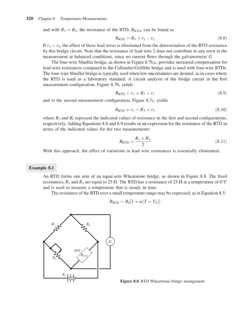
An RTD forms one arm of an equal-arm Wheatstone bridge, as shown in Figure 8.8. The fixed
resistances, R 2 and R 3 are equal to 25 V. The RTD has a resistance of 25 V at a temperature of 0
C
and is used to measure a temperature that is steady in time.
The resistance of the RTD over a small temperature range may be expressed, as in Equation 8.5:
R RTD ¼ R 0 1 þ a T À T 0
ð
Þ
½
R 2
R 1
R 3
E i
G
RTD
R RTD
Figure 8.8 RTD Wheatstone bridge arrangement.
320 Chapter 8 Temperature Measurements
14:53:56 Page 320
and with R 1 ¼ R 2 , the resistance of the RTD, R RTD , can be found as
R RTD ¼ R 3 þ r 1 À r 3
ð8:8Þ
If r 1 ¼ r 3 , the effect of these lead wires is eliminated from the determination of the RTD resistance
by this bridge circuit. Note that the resistance of lead wire 2 does not contribute to any error in the
measurement at balanced conditions, since no current flows through the galvanometer G.
The four-wire Mueller bridge, as shown in Figure 8.7b,c, provides increased compensation for
lead-wire resistances compared to the Callendar-Griffiths bridge and is used with four-wire RTDs.
The four-wire Mueller bridge is typically used when low uncertainties are desired, as in cases where
the RTD is used as a laboratory standard. A circuit analysis of the bridge circuit in the first
measurement configuration, Figure 8.7b, yields
R RTD þ r 3 ¼ R 3 þ r 1
ð8:9Þ
and in the second measurement configuration, Figure 8.7c, yields
R RTD þ r 1 ¼ R
0
3 þ r 3
ð8:10Þ
where R 3 and R
0
3 represent the indicated values of resistance in the first and second configurations,
respectively. Adding Equations 8.8 and 8.9 results in an expression for the resistance of the RTD in
terms of the indicated values for the two measurements:
R RTD ¼
R 3 þ R
0
3
2
ð8:11Þ
With this approach, the effect of variations in lead wire resistances is essentially eliminated.
Example 8.1
An RTD forms one arm of an equal-arm Wheatstone bridge, as shown in Figure 8.8. The fixed
resistances, R 2 and R 3 are equal to 25 V. The RTD has a resistance of 25 V at a temperature of 0
C
and is used to measure a temperature that is steady in time.
The resistance of the RTD over a small temperature range may be expressed, as in Equation 8.5:
R RTD ¼ R 0 1 þ a T À T 0
ð
Þ
½
R 2
R 1
R 3
E i
G
RTD
R RTD
Figure 8.8 RTD Wheatstone bridge arrangement.
320 Chapter 8 Temperature Measurements