

E1C07 09/14/2010
14:43:51 Page 293
7.9 DIGITAL INPUT–OUTPUT COMMUNICATION
Certain standards exist for the manner in which digital information is communicated between digital
devices (6,7). Serial communication methods transmit data bit by bit. Parallel communication
methods transmit data in simultaneous groups of bits, for example, byte by byte. Both methods use a
handshake, an interface protocol that initiates, allows, and terminates the data transfer between
devices and TTL-level signals. Most lab equipment can be equipped to communicate by at least one
of these means, and standards have been defined to codify communications between devices of
different manufacturers. Standards continuously evolve, so the present discussion focuses on
concepts and application of representative standards.
Serial Communications: RS-232C
The RS-232C protocol, which was initially set up to translate signals between telephone lines and
computers via a modem (modulator-demodulator), remains a well-used interface for communication between a computer and any serial device. Basically, this protocol allows two-way communication using two single-ended signal (þ) wires, noted as TRANSMIT and RECEIVE, between data
communications equipment (DCE), such as an instrument, and data terminal equipment (DTE),
such as the data acquisition system or computer. These two signals are analogous to a telephone’s
mouthpiece and earpiece signals. A signal GROUND wire allows signal return (À) paths.
Most lab computers have an RS-232C–compatible I/O port. The popularity of this interface is
due to the wide range of equipment that can utilize it. Either a 9-pin or 25-pin connector can be used.
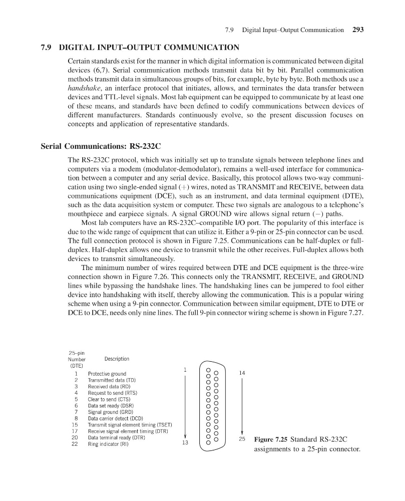
The full connection protocol is shown in Figure 7.25. Communications can be half-duplex or fullduplex. Half-duplex allows one device to transmit while the other receives. Full-duplex allows both
devices to transmit simultaneously.
The minimum number of wires required between DTE and DCE equipment is the three-wire
connection shown in Figure 7.26. This connects only the TRANSMIT, RECEIVE, and GROUND
lines while bypassing the handshake lines. The handshaking lines can be jumpered to fool either
device into handshaking with itself, thereby allowing the communication. This is a popular wiring
scheme when using a 9-pin connector. Communication between similar equipment, DTE to DTE or
DCE to DCE, needs only nine lines. The full 9-pin connector wiring scheme is shown in Figure 7.27.
Description
Protective ground
Transmitted data (TD)
Received data (RD)
Request to send (RTS)
Clear to send (CTS)
Data set ready (DSR)
Signal ground (GRD)
Data carrier detect (DCD)
Transmit signal element timing (TSET)
Receive signal element timing (DTR)
Data terminal ready (DTR)
Ring indicator (RI)
1
13
14
25
25–pin
Number
(DTE)
1
2
3
4
5
6
7
8
15
17
20
22
Figure 7.25 Standard RS-232C
assignments to a 25-pin connector.
7.9 Digital Input–Output Communication 293
14:43:51 Page 293
7.9 DIGITAL INPUT–OUTPUT COMMUNICATION
Certain standards exist for the manner in which digital information is communicated between digital
devices (6,7). Serial communication methods transmit data bit by bit. Parallel communication
methods transmit data in simultaneous groups of bits, for example, byte by byte. Both methods use a
handshake, an interface protocol that initiates, allows, and terminates the data transfer between
devices and TTL-level signals. Most lab equipment can be equipped to communicate by at least one
of these means, and standards have been defined to codify communications between devices of
different manufacturers. Standards continuously evolve, so the present discussion focuses on
concepts and application of representative standards.
Serial Communications: RS-232C
The RS-232C protocol, which was initially set up to translate signals between telephone lines and
computers via a modem (modulator-demodulator), remains a well-used interface for communication between a computer and any serial device. Basically, this protocol allows two-way communication using two single-ended signal (þ) wires, noted as TRANSMIT and RECEIVE, between data
communications equipment (DCE), such as an instrument, and data terminal equipment (DTE),
such as the data acquisition system or computer. These two signals are analogous to a telephone’s
mouthpiece and earpiece signals. A signal GROUND wire allows signal return (À) paths.
Most lab computers have an RS-232C–compatible I/O port. The popularity of this interface is
due to the wide range of equipment that can utilize it. Either a 9-pin or 25-pin connector can be used.
The full connection protocol is shown in Figure 7.25. Communications can be half-duplex or fullduplex. Half-duplex allows one device to transmit while the other receives. Full-duplex allows both
devices to transmit simultaneously.
The minimum number of wires required between DTE and DCE equipment is the three-wire
connection shown in Figure 7.26. This connects only the TRANSMIT, RECEIVE, and GROUND
lines while bypassing the handshake lines. The handshaking lines can be jumpered to fool either
device into handshaking with itself, thereby allowing the communication. This is a popular wiring
scheme when using a 9-pin connector. Communication between similar equipment, DTE to DTE or
DCE to DCE, needs only nine lines. The full 9-pin connector wiring scheme is shown in Figure 7.27.
Description
Protective ground
Transmitted data (TD)
Received data (RD)
Request to send (RTS)
Clear to send (CTS)
Data set ready (DSR)
Signal ground (GRD)
Data carrier detect (DCD)
Transmit signal element timing (TSET)
Receive signal element timing (DTR)
Data terminal ready (DTR)
Ring indicator (RI)
1
13
14
25
25–pin
Number
(DTE)
1
2
3
4
5
6
7
8
15
17
20
22
Figure 7.25 Standard RS-232C
assignments to a 25-pin connector.
7.9 Digital Input–Output Communication 293