

E1C07 09/14/2010
14:43:49 Page 273
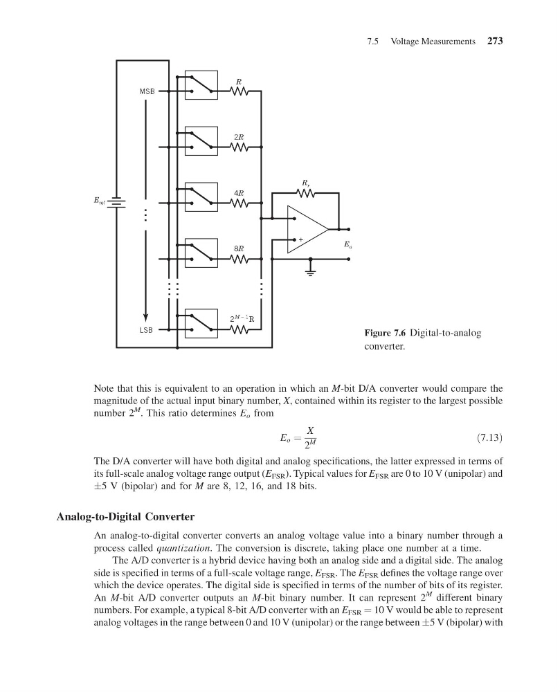
Note that this is equivalent to an operation in which an M-bit D/A converter would compare the
magnitude of the actual input binary number, X, contained within its register to the largest possible
number 2
M . This ratio determines E o from
E o ¼
X
2
M
ð7:13Þ
The D/A converter will have both digital and analog specifications, the latter expressed in terms of
its full-scale analog voltage range output (E FSR ). Typical values for E FSR are 0 to 10 V (unipolar) and
Æ5 V (bipolar) and for M are 8, 12, 16, and 18 bits.
Analog-to-Digital Converter
An analog-to-digital converter converts an analog voltage value into a binary number through a
process called quantization. The conversion is discrete, taking place one number at a time.
The A/D converter is a hybrid device having both an analog side and a digital side. The analog
side is specified in terms of a full-scale voltage range, E FSR . The E FSR defines the voltage range over
which the device operates. The digital side is specified in terms of the number of bits of its register.
An M-bit A/D converter outputs an M-bit binary number. It can represent 2
M different binary
numbers. For example, a typical 8-bit A/D converter with an E FSR ¼ 10 V would be able to represent
analog voltages in the range between 0 and 10 V (unipolar) or the range between Æ5 V (bipolar) with
MSB
2
R
M – 1
LSB
8R
4R
2R
R
E o
R r
E ref
+
... ...
...
...
Figure 7.6 Digital-to-analog
converter.
7.5 Voltage Measurements 273
14:43:49 Page 273
Note that this is equivalent to an operation in which an M-bit D/A converter would compare the
magnitude of the actual input binary number, X, contained within its register to the largest possible
number 2
M . This ratio determines E o from
E o ¼
X
2
M
ð7:13Þ
The D/A converter will have both digital and analog specifications, the latter expressed in terms of
its full-scale analog voltage range output (E FSR ). Typical values for E FSR are 0 to 10 V (unipolar) and
Æ5 V (bipolar) and for M are 8, 12, 16, and 18 bits.
Analog-to-Digital Converter
An analog-to-digital converter converts an analog voltage value into a binary number through a
process called quantization. The conversion is discrete, taking place one number at a time.
The A/D converter is a hybrid device having both an analog side and a digital side. The analog
side is specified in terms of a full-scale voltage range, E FSR . The E FSR defines the voltage range over
which the device operates. The digital side is specified in terms of the number of bits of its register.
An M-bit A/D converter outputs an M-bit binary number. It can represent 2
M different binary
numbers. For example, a typical 8-bit A/D converter with an E FSR ¼ 10 V would be able to represent
analog voltages in the range between 0 and 10 V (unipolar) or the range between Æ5 V (bipolar) with
MSB
2
R
M – 1
LSB
8R
4R
2R
R
E o
R r
E ref
+
... ...
...
...
Figure 7.6 Digital-to-analog
converter.
7.5 Voltage Measurements 273