

E1C07 09/14/2010
14:43:49 Page 272
Closed = HIGH (5 V)
5 V
+5 V
+5 V
1
0 V
0
5 V
1
0 V
0
Open = LOW (0 V)
(5 V) HIGH
(0 V) LOW
Control logic
Switch
Simple 4-bit register
Control logic
0
0
1
Time
1
E
(b)
(a)
(c)
δt
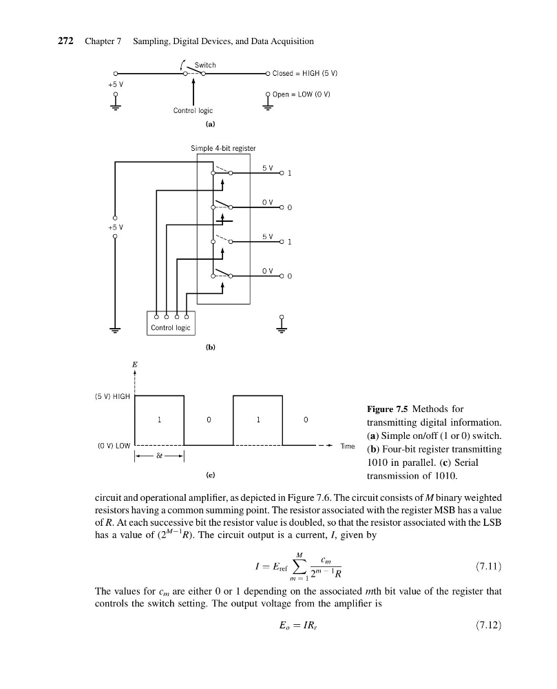
Figure 7.5 Methods for
transmitting digital information.
(a) Simple on/off (1 or 0) switch.
(b) Four-bit register transmitting
1010 in parallel. (c) Serial
transmission of 1010.
circuit and operational amplifier, as depicted in Figure 7.6. The circuit consists of M binary weighted
resistors having a common summing point. The resistor associated with the register MSB has a value
of R. At each successive bit the resistor value is doubled, so that the resistor associated with the LSB
has a value of (2
MÀ1
R). The circuit output is a current, I, given by
I ¼ E ref
X M
m ¼ 1
c m
2
m À 1
R
ð7:11Þ
The values for c m are either 0 or 1 depending on the associated mth bit value of the register that
controls the switch setting. The output voltage from the amplifier is
E o ¼ IR r
ð7:12Þ
272 Chapter 7 Sampling, Digital Devices, and Data Acquisition
14:43:49 Page 272
Closed = HIGH (5 V)
5 V
+5 V
+5 V
1
0 V
0
5 V
1
0 V
0
Open = LOW (0 V)
(5 V) HIGH
(0 V) LOW
Control logic
Switch
Simple 4-bit register
Control logic
0
0
1
Time
1
E
(b)
(a)
(c)
δt
Figure 7.5 Methods for
transmitting digital information.
(a) Simple on/off (1 or 0) switch.
(b) Four-bit register transmitting
1010 in parallel. (c) Serial
transmission of 1010.
circuit and operational amplifier, as depicted in Figure 7.6. The circuit consists of M binary weighted
resistors having a common summing point. The resistor associated with the register MSB has a value
of R. At each successive bit the resistor value is doubled, so that the resistor associated with the LSB
has a value of (2
MÀ1
R). The circuit output is a current, I, given by
I ¼ E ref
X M
m ¼ 1
c m
2
m À 1
R
ð7:11Þ
The values for c m are either 0 or 1 depending on the associated mth bit value of the register that
controls the switch setting. The output voltage from the amplifier is
E o ¼ IR r
ð7:12Þ
272 Chapter 7 Sampling, Digital Devices, and Data Acquisition