

E1C06 09/14/2010
11:55:8 Page 255
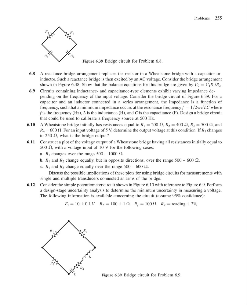
6.8 A reactance bridge arrangement replaces the resistor in a Wheatstone bridge with a capacitor or
inductor. Such a reactance bridge is then excited by an AC voltage. Consider the bridge arrangement
shown in Figure 6.38. Show that the balance equations for this bridge are given by C 2 ¼ C 1 R 1 /R 2 .
6.9 Circuits containing inductance- and capacitance-type elements exhibit varying impedance depending on the frequency of the input voltage. Consider the bridge circuit of Figure 6.39. For a
capacitor and an inductor connected in a series arrangement, the impedance is a function of
frequency, such that a minimum impedance occurs at the resonance frequency f ¼ 1=2p
ffiffiffiffiffiffi
LC
p
where
f is the frequency (Hz), L is the inductance (H), and C is the capacitance (F). Design a bridge circuit
that could be used to calibrate a frequency source at 500 Hz.
6.10 A Wheatstone bridge initially has resistances equal to R 1 ¼ 200 V, R 2 ¼ 400 V, R 3 ¼ 500 V, and
R 4 ¼ 600 V. For an input voltage of 5 V, determine the output voltage at this condition. If R 1 changes
to 250 V, what is the bridge output?
6.11 Construct a plot of the voltage output of a Wheatstone bridge having all resistances initially equal to
500 V, with a voltage input of 10 V for the following cases:
a. R 1 changes over the range 500 – 1000 V.
b. R 1 and R 2 change equally, but in opposite directions, over the range 500 – 600 V.
c. R 1 and R 3 change equally over the range 500 – 600 V.
Discuss the possible implications of these plots for using bridge circuits for measurements with
single and multiple transducers connected as arms of the bridge.
6.12 Consider the simple potentiometer circuit shown in Figure 6.10 with reference to Figure 6.9. Perform
a design-stage uncertainty analysis to determine the minimum uncertainty in measuring a voltage.
The following information is available concerning the circuit (assume 95% confidence):
E i ¼ 10 Æ 0:1 V R T ¼ 100 Æ 1 V R g ¼ 100 V R x ¼ reading Æ 2%
C 1
R 1
C 2
R 2
Figure 6.38 Bridge circuit for Problem 6.8.
C
L
R 4
R 1
R 3
R 2
Figure 6.39 Bridge circuit for Problem 6.9.
Problems 255
11:55:8 Page 255
6.8 A reactance bridge arrangement replaces the resistor in a Wheatstone bridge with a capacitor or
inductor. Such a reactance bridge is then excited by an AC voltage. Consider the bridge arrangement
shown in Figure 6.38. Show that the balance equations for this bridge are given by C 2 ¼ C 1 R 1 /R 2 .
6.9 Circuits containing inductance- and capacitance-type elements exhibit varying impedance depending on the frequency of the input voltage. Consider the bridge circuit of Figure 6.39. For a
capacitor and an inductor connected in a series arrangement, the impedance is a function of
frequency, such that a minimum impedance occurs at the resonance frequency f ¼ 1=2p
ffiffiffiffiffiffi
LC
p
where
f is the frequency (Hz), L is the inductance (H), and C is the capacitance (F). Design a bridge circuit
that could be used to calibrate a frequency source at 500 Hz.
6.10 A Wheatstone bridge initially has resistances equal to R 1 ¼ 200 V, R 2 ¼ 400 V, R 3 ¼ 500 V, and
R 4 ¼ 600 V. For an input voltage of 5 V, determine the output voltage at this condition. If R 1 changes
to 250 V, what is the bridge output?
6.11 Construct a plot of the voltage output of a Wheatstone bridge having all resistances initially equal to
500 V, with a voltage input of 10 V for the following cases:
a. R 1 changes over the range 500 – 1000 V.
b. R 1 and R 2 change equally, but in opposite directions, over the range 500 – 600 V.
c. R 1 and R 3 change equally over the range 500 – 600 V.
Discuss the possible implications of these plots for using bridge circuits for measurements with
single and multiple transducers connected as arms of the bridge.
6.12 Consider the simple potentiometer circuit shown in Figure 6.10 with reference to Figure 6.9. Perform
a design-stage uncertainty analysis to determine the minimum uncertainty in measuring a voltage.
The following information is available concerning the circuit (assume 95% confidence):
E i ¼ 10 Æ 0:1 V R T ¼ 100 Æ 1 V R g ¼ 100 V R x ¼ reading Æ 2%
C 1
R 1
C 2
R 2
Figure 6.38 Bridge circuit for Problem 6.8.
C
L
R 4
R 1
R 3
R 2
Figure 6.39 Bridge circuit for Problem 6.9.
Problems 255