

E1C03 09/14/2010
15:24:54 Page 104
3.4 TRANSFER FUNCTIONS
Consider the schematic representation in Figure 3.19. The measurement system operates on the
input signal, F(t), by some function, G(s), so as to indicate the output signal, y(t). This operation can
be explored by taking the Laplace transform of both sides of Equation 3.4, which describes the
general first-order measurement system. One obtains
Y s
ð Þ ¼
1
ts þ 1
KF s
ð Þ þ
y 0
ts þ 1
where y 0 ¼ y(0). This can be rewritten as
Y s
ð Þ ¼ G s
ð ÞKF s
ð Þ þ G s
ð ÞQ s
ð Þ
ð3:24Þ
where G(s) is the transfer function of the first-order system given by
G s
ð Þ ¼
1
ts þ 1
ð3:25Þ
and Q(s) is the system initial state function. Because it includes KF(s), the first term on the right side
of Equation 3.24 contains the information that describes the steady response of the measurement
6
.
0
1
.
0
5%
1.05
0.95
1.0
2.0
0.1
1.0
2.0
n
Magnitude ratio (
)
= 0.7
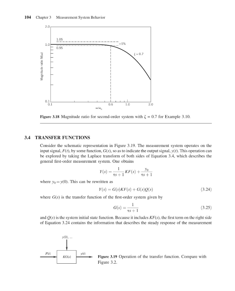
Figure 3.18 Magnitude ratio for second-order system with z = 0.7 for Example 3.10.
y(0), ...
F(t)
y(t)
KG(s)
Figure 3.19 Operation of the transfer function. Compare with
Figure 3.2.
104 Chapter 3 Measurement System Behavior
15:24:54 Page 104
3.4 TRANSFER FUNCTIONS
Consider the schematic representation in Figure 3.19. The measurement system operates on the
input signal, F(t), by some function, G(s), so as to indicate the output signal, y(t). This operation can
be explored by taking the Laplace transform of both sides of Equation 3.4, which describes the
general first-order measurement system. One obtains
Y s
ð Þ ¼
1
ts þ 1
KF s
ð Þ þ
y 0
ts þ 1
where y 0 ¼ y(0). This can be rewritten as
Y s
ð Þ ¼ G s
ð ÞKF s
ð Þ þ G s
ð ÞQ s
ð Þ
ð3:24Þ
where G(s) is the transfer function of the first-order system given by
G s
ð Þ ¼
1
ts þ 1
ð3:25Þ
and Q(s) is the system initial state function. Because it includes KF(s), the first term on the right side
of Equation 3.24 contains the information that describes the steady response of the measurement
6
.
0
1
.
0
5%
1.05
0.95
1.0
2.0
0.1
1.0
2.0
n
Magnitude ratio (
)
= 0.7
Figure 3.18 Magnitude ratio for second-order system with z = 0.7 for Example 3.10.
y(0), ...
F(t)
y(t)
KG(s)
Figure 3.19 Operation of the transfer function. Compare with
Figure 3.2.
104 Chapter 3 Measurement System Behavior