

30
2 Basic Elements of Spintronics
2.3.4 Sustainability of Spin Polarization in Paramagnet
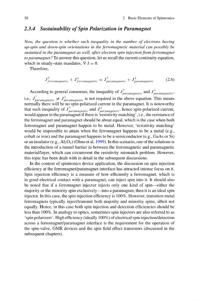
Now, the question is whether such inequality in the number of electrons having
up-spin and down-spin orientations in the ferromagnetic material can possibly be
sustained in the paramagnet as well, after electron spin injection from ferromagnet
to paramagnet? To answer this question, let us recall the current continuity equation,
which in steady-state mandates, ∇·J = 0.
Therefore,
J
↑
f erromagnetic + J
↓
f erromagnetic = J
↑
paramagnetic + J
↓
paramagnetic
(2.6)
According to general consensus, the inequality of J
↑
paramagnetic and J
↓
paramagnetic ,
i.e., J
↑
paramagnetic = J
↓
paramagnetic is not required in the above equation. This means
normally there will be no spin-polarized current in the paramagnet. It is noteworthy
that such inequality of J
↑
paramagnetic and J
↓
paramagnetic , hence spin-polarized current,
would appear in the paramagnet if there is ‘resistivity matching’, i.e., the resistance of
the ferromagnet and paramagnet should be about equal, which is the case when both
ferromagnet and paramagnet happen to be metal. However, ‘resistivity matching’
would be impossible to attain when the ferromagnet happens to be a metal (e.g.,
cobalt or iron) and the paramagnet happens to be a semiconductor (e.g., GaAs or Si)
or an insulator (e.g., Al 2 O 3 ) (Ohno et al. 1999). In this scenario, one of the solutions is
the introduction of a tunnel barrier in between the ferromagnetic and paramagnetic
material/layer, which can circumvent the resistivity mismatch problem. However,
this topic has been dealt with in detail in the subsequent discussions.
In the context of spintronics device application, the discussion on spin injection
efficiency at the ferromagnet/paramagnet interface has attracted intense focus on it.
Spin injection efficiency is a measure of how efficiently a ferromagnet, which is
in good electrical contact with a paramagnet, can inject spin into it. It should also
be noted that if a ferromagnet injector injects only one kind of spin—either the
majority or the minority spin exclusively—into a paramagnet, then it is an ideal spin
injector. In this case, the spin injection efficiency is 100%. However, transition metal
ferromagnets typically inject/transmit both majority and minority spins, albeit not
equally. Hence, in this case both spin injection and detection efficiencies should be
less than 100%. In analogy to optics, sometimes spin injectors are also referred to as
‘spin polarizers’. High efficiency (ideally 100%) of electrical spin injection/detection
across a ferromagnet/paramagnet interface is the requirement for the operation of
the spin-valve, GMR devices and the spin field effect transistors (discussed in the
subsequent chapters).
2 Basic Elements of Spintronics
2.3.4 Sustainability of Spin Polarization in Paramagnet
Now, the question is whether such inequality in the number of electrons having
up-spin and down-spin orientations in the ferromagnetic material can possibly be
sustained in the paramagnet as well, after electron spin injection from ferromagnet
to paramagnet? To answer this question, let us recall the current continuity equation,
which in steady-state mandates, ∇·J = 0.
Therefore,
J
↑
f erromagnetic + J
↓
f erromagnetic = J
↑
paramagnetic + J
↓
paramagnetic
(2.6)
According to general consensus, the inequality of J
↑
paramagnetic and J
↓
paramagnetic ,
i.e., J
↑
paramagnetic = J
↓
paramagnetic is not required in the above equation. This means
normally there will be no spin-polarized current in the paramagnet. It is noteworthy
that such inequality of J
↑
paramagnetic and J
↓
paramagnetic , hence spin-polarized current,
would appear in the paramagnet if there is ‘resistivity matching’, i.e., the resistance of
the ferromagnet and paramagnet should be about equal, which is the case when both
ferromagnet and paramagnet happen to be metal. However, ‘resistivity matching’
would be impossible to attain when the ferromagnet happens to be a metal (e.g.,
cobalt or iron) and the paramagnet happens to be a semiconductor (e.g., GaAs or Si)
or an insulator (e.g., Al 2 O 3 ) (Ohno et al. 1999). In this scenario, one of the solutions is
the introduction of a tunnel barrier in between the ferromagnetic and paramagnetic
material/layer, which can circumvent the resistivity mismatch problem. However,
this topic has been dealt with in detail in the subsequent discussions.
In the context of spintronics device application, the discussion on spin injection
efficiency at the ferromagnet/paramagnet interface has attracted intense focus on it.
Spin injection efficiency is a measure of how efficiently a ferromagnet, which is
in good electrical contact with a paramagnet, can inject spin into it. It should also
be noted that if a ferromagnet injector injects only one kind of spin—either the
majority or the minority spin exclusively—into a paramagnet, then it is an ideal spin
injector. In this case, the spin injection efficiency is 100%. However, transition metal
ferromagnets typically inject/transmit both majority and minority spins, albeit not
equally. Hence, in this case both spin injection and detection efficiencies should be
less than 100%. In analogy to optics, sometimes spin injectors are also referred to as
‘spin polarizers’. High efficiency (ideally 100%) of electrical spin injection/detection
across a ferromagnet/paramagnet interface is the requirement for the operation of
the spin-valve, GMR devices and the spin field effect transistors (discussed in the
subsequent chapters).