

234
10 Spintronics Applications
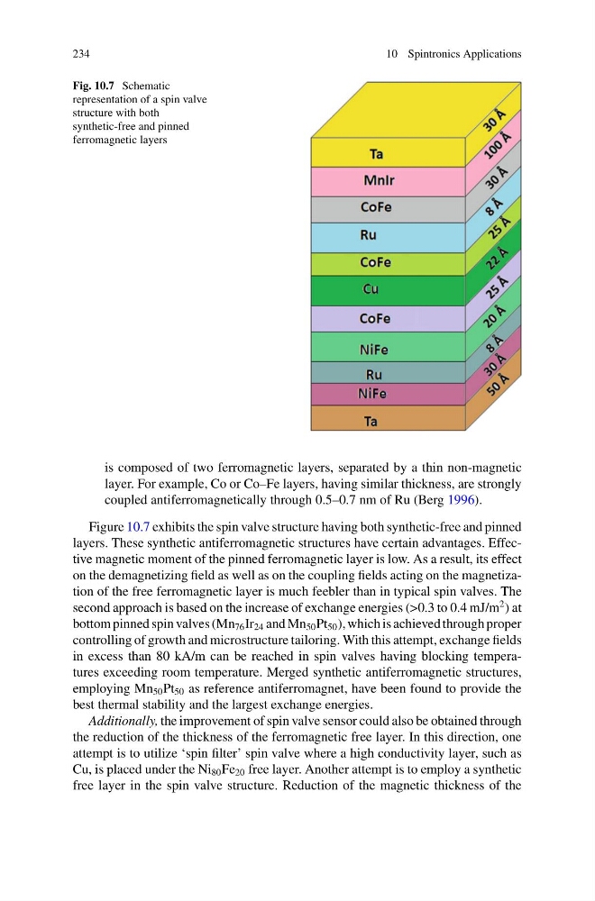
Fig. 10.7 Schematic
representation of a spin valve
structure with both
synthetic-free and pinned
ferromagnetic layers
is composed of two ferromagnetic layers, separated by a thin non-magnetic
layer. For example, Co or Co–Fe layers, having similar thickness, are strongly
coupled antiferromagnetically through 0.5–0.7 nm of Ru (Berg 1996).
Figure 10.7 exhibits the spin valve structure having both synthetic-free and pinned
layers. These synthetic antiferromagnetic structures have certain advantages. Effective magnetic moment of the pinned ferromagnetic layer is low. As a result, its effect
on the demagnetizing field as well as on the coupling fields acting on the magnetization of the free ferromagnetic layer is much feebler than in typical spin valves. The
second approach is based on the increase of exchange energies (>0.3 to 0.4 mJ/m
2 ) at
bottom pinned spin valves (Mn 76 Ir 24 and Mn 50 Pt 50 ), which is achieved through proper
controlling of growth and microstructure tailoring. With this attempt, exchange fields
in excess than 80 kA/m can be reached in spin valves having blocking temperatures exceeding room temperature. Merged synthetic antiferromagnetic structures,
employing Mn 50 Pt 50 as reference antiferromagnet, have been found to provide the
best thermal stability and the largest exchange energies.
Additionally, the improvement of spin valve sensor could also be obtained through
the reduction of the thickness of the ferromagnetic free layer. In this direction, one
attempt is to utilize ‘spin filter’ spin valve where a high conductivity layer, such as
Cu, is placed under the Ni 80 Fe 20 free layer. Another attempt is to employ a synthetic
free layer in the spin valve structure. Reduction of the magnetic thickness of the
10 Spintronics Applications
Fig. 10.7 Schematic
representation of a spin valve
structure with both
synthetic-free and pinned
ferromagnetic layers
is composed of two ferromagnetic layers, separated by a thin non-magnetic
layer. For example, Co or Co–Fe layers, having similar thickness, are strongly
coupled antiferromagnetically through 0.5–0.7 nm of Ru (Berg 1996).
Figure 10.7 exhibits the spin valve structure having both synthetic-free and pinned
layers. These synthetic antiferromagnetic structures have certain advantages. Effective magnetic moment of the pinned ferromagnetic layer is low. As a result, its effect
on the demagnetizing field as well as on the coupling fields acting on the magnetization of the free ferromagnetic layer is much feebler than in typical spin valves. The
second approach is based on the increase of exchange energies (>0.3 to 0.4 mJ/m
2 ) at
bottom pinned spin valves (Mn 76 Ir 24 and Mn 50 Pt 50 ), which is achieved through proper
controlling of growth and microstructure tailoring. With this attempt, exchange fields
in excess than 80 kA/m can be reached in spin valves having blocking temperatures exceeding room temperature. Merged synthetic antiferromagnetic structures,
employing Mn 50 Pt 50 as reference antiferromagnet, have been found to provide the
best thermal stability and the largest exchange energies.
Additionally, the improvement of spin valve sensor could also be obtained through
the reduction of the thickness of the ferromagnetic free layer. In this direction, one
attempt is to utilize ‘spin filter’ spin valve where a high conductivity layer, such as
Cu, is placed under the Ni 80 Fe 20 free layer. Another attempt is to employ a synthetic
free layer in the spin valve structure. Reduction of the magnetic thickness of the