

146
6 Magnetic Domain Wall Motion
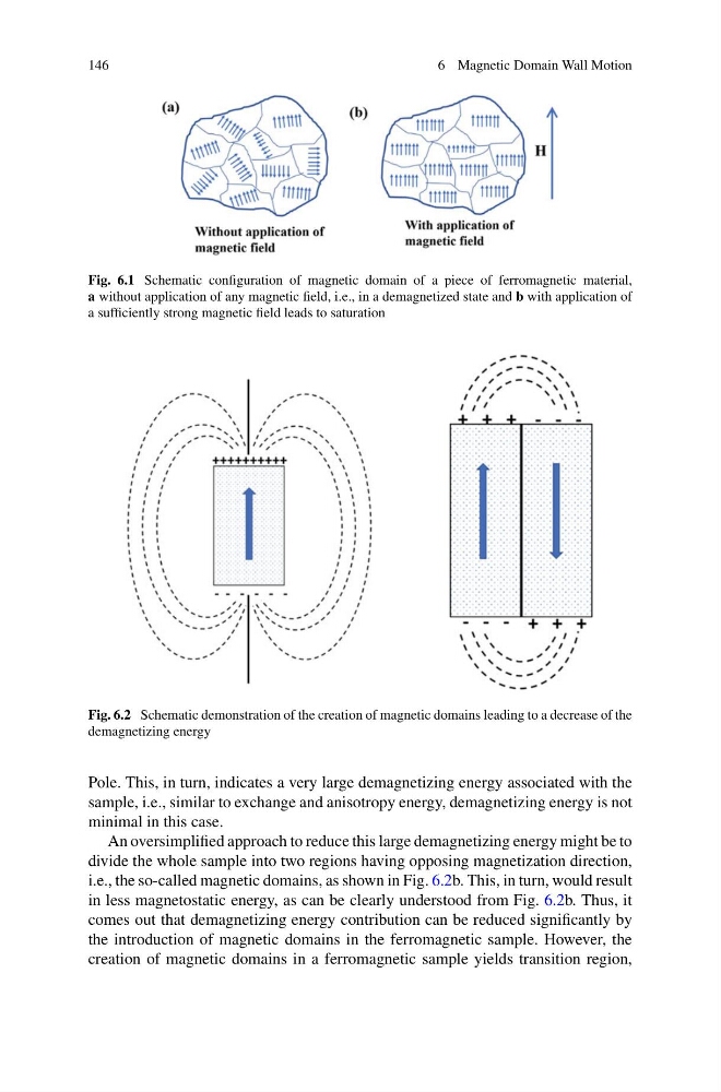
Fig. 6.1 Schematic configuration of magnetic domain of a piece of ferromagnetic material,
a without application of any magnetic field, i.e., in a demagnetized state and b with application of
a sufficiently strong magnetic field leads to saturation
Fig. 6.2 Schematic demonstration of the creation of magnetic domains leading to a decrease of the
demagnetizing energy
Pole. This, in turn, indicates a very large demagnetizing energy associated with the
sample, i.e., similar to exchange and anisotropy energy, demagnetizing energy is not
minimal in this case.
An oversimplified approach to reduce this large demagnetizing energy might be to
divide the whole sample into two regions having opposing magnetization direction,
i.e., the so-called magnetic domains, as shown in Fig. 6.2b. This, in turn, would result
in less magnetostatic energy, as can be clearly understood from Fig. 6.2b. Thus, it
comes out that demagnetizing energy contribution can be reduced significantly by
the introduction of magnetic domains in the ferromagnetic sample. However, the
creation of magnetic domains in a ferromagnetic sample yields transition region,
6 Magnetic Domain Wall Motion
Fig. 6.1 Schematic configuration of magnetic domain of a piece of ferromagnetic material,
a without application of any magnetic field, i.e., in a demagnetized state and b with application of
a sufficiently strong magnetic field leads to saturation
Fig. 6.2 Schematic demonstration of the creation of magnetic domains leading to a decrease of the
demagnetizing energy
Pole. This, in turn, indicates a very large demagnetizing energy associated with the
sample, i.e., similar to exchange and anisotropy energy, demagnetizing energy is not
minimal in this case.
An oversimplified approach to reduce this large demagnetizing energy might be to
divide the whole sample into two regions having opposing magnetization direction,
i.e., the so-called magnetic domains, as shown in Fig. 6.2b. This, in turn, would result
in less magnetostatic energy, as can be clearly understood from Fig. 6.2b. Thus, it
comes out that demagnetizing energy contribution can be reduced significantly by
the introduction of magnetic domains in the ferromagnetic sample. However, the
creation of magnetic domains in a ferromagnetic sample yields transition region,