

136
5 Spin-Transfer Torque
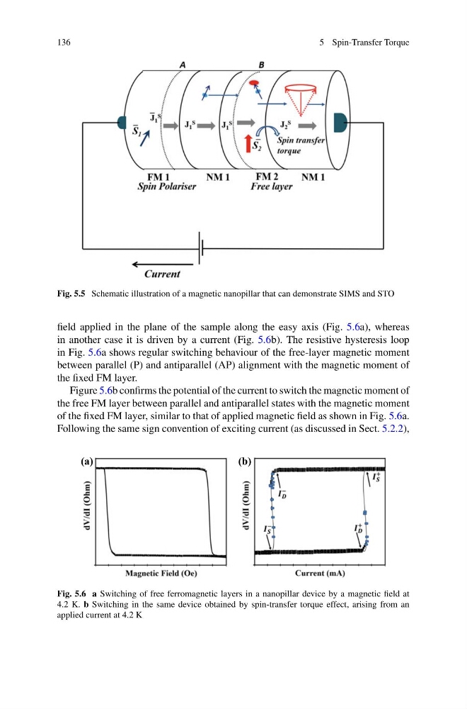
Fig. 5.5 Schematic illustration of a magnetic nanopillar that can demonstrate SIMS and STO
field applied in the plane of the sample along the easy axis (Fig. 5.6a), whereas
in another case it is driven by a current (Fig. 5.6b). The resistive hysteresis loop
in Fig. 5.6a shows regular switching behaviour of the free-layer magnetic moment
between parallel (P) and antiparallel (AP) alignment with the magnetic moment of
the fixed FM layer.
Figure 5.6b confirms the potential of the current to switch the magnetic moment of
the free FM layer between parallel and antiparallel states with the magnetic moment
of the fixed FM layer, similar to that of applied magnetic field as shown in Fig. 5.6a.
Following the same sign convention of exciting current (as discussed in Sect. 5.2.2),
(a)
(b)
Fig. 5.6 a Switching of free ferromagnetic layers in a nanopillar device by a magnetic field at
4.2 K. b Switching in the same device obtained by spin-transfer torque effect, arising from an
applied current at 4.2 K
5 Spin-Transfer Torque
Fig. 5.5 Schematic illustration of a magnetic nanopillar that can demonstrate SIMS and STO
field applied in the plane of the sample along the easy axis (Fig. 5.6a), whereas
in another case it is driven by a current (Fig. 5.6b). The resistive hysteresis loop
in Fig. 5.6a shows regular switching behaviour of the free-layer magnetic moment
between parallel (P) and antiparallel (AP) alignment with the magnetic moment of
the fixed FM layer.
Figure 5.6b confirms the potential of the current to switch the magnetic moment of
the free FM layer between parallel and antiparallel states with the magnetic moment
of the fixed FM layer, similar to that of applied magnetic field as shown in Fig. 5.6a.
Following the same sign convention of exciting current (as discussed in Sect. 5.2.2),
(a)
(b)
Fig. 5.6 a Switching of free ferromagnetic layers in a nanopillar device by a magnetic field at
4.2 K. b Switching in the same device obtained by spin-transfer torque effect, arising from an
applied current at 4.2 K