

114
4 Tunnelling Magnetoresistance (TMR)
where dI/dV = G is the zero-bias conductance of the tunnelling junction. It is quite
evident from Eq. 4.18 that in the low-bias regime current should be proportional to
the voltage, i.e., I ∝ V, which implies the ohmic behaviour of the junction.
Jullière adopted Eq. 4.18 to explain the magnitude of tunnelling magnetoresistance
in case of a MTJ, consisting of ferromagnetic (FM)–insulator (I)–ferromagnetic (FM)
layer structures. As it has already been discussed in case of ferromagnetic electrodes,
densities of states related to the majority (spin parallel to the magnetization) and
minority (spin antiparallel to the magnetization) spin electrons, denoted by D↑(E)
and D↓(E), respectively, are different. This is because the up-spin and down-spin
energy bands are shifted with respect to one another along the energy axis by exchange
interaction. In an attempt to account a crucial point of concern that tunnelling current
depends on the relative orientation of magnetization of the ferromagnetic electrodes,
an additional assumption that electron spin is conserved in tunnelling has been
proposed by Jullière. Thus, tunnelling of up-spin and down-spin electrons can be
considered as two independent channels of current resembling two wires connected
parallelly. This implies that the tunnelling current flows in two separate up-spin
and down-spin channels, which is the well-known two-current model. Such model
is also successfully employed for the interpretation of the giant magnetoresistance
effect, which is closely related to TMR effect, in magnetic multilayers. As generally
considered in any kind of spin valve effect, the magnetization of the ferromagnetic
electrodes is antiparallel without application of any magnetic field, i.e., when the
magnetic field is zero and parallel under the application of a saturating magnetic
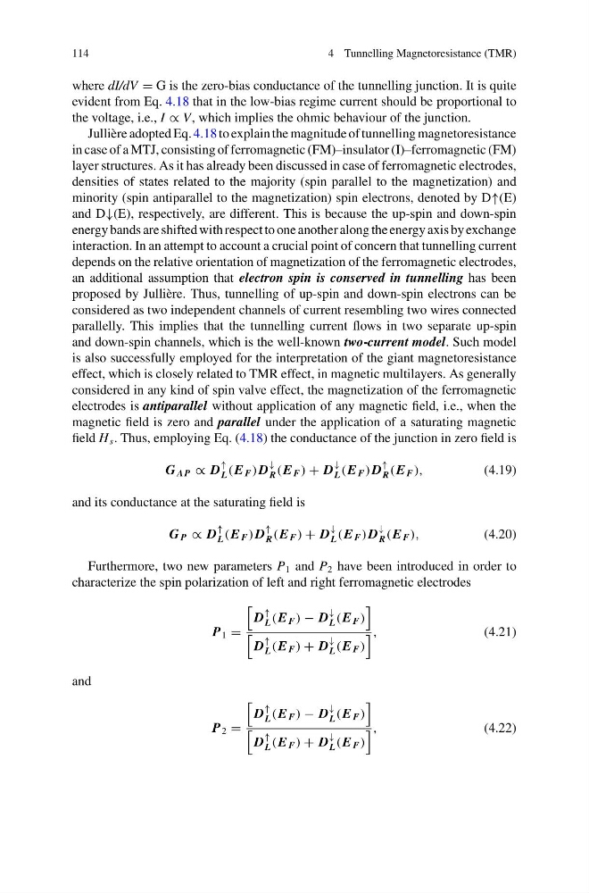
field H s . Thus, employing Eq. (4.18) the conductance of the junction in zero field is
G AP ∝ D
↑
L (E F ) D
↓
R (E F ) + D
↓
L (E F ) D
↑
R (E F ),
(4.19)
and its conductance at the saturating field is
G P ∝ D
↑
L (E F ) D
↑
R (E F ) + D
↓
L (E F ) D
↓
R (E F ),
(4.20)
Furthermore, two new parameters P 1 and P 2 have been introduced in order to
characterize the spin polarization of left and right ferromagnetic electrodes
P 1 =
D
↑
L (E F ) − D
↓
L (E F )
D
↑
L (E F ) + D
↓
L (E F )
,
(4.21)
and
P 2 =
D
↑
L (E F ) − D
↓
L (E F )
D
↑
L (E F ) + D
↓
L (E F )
,
(4.22)
4 Tunnelling Magnetoresistance (TMR)
where dI/dV = G is the zero-bias conductance of the tunnelling junction. It is quite
evident from Eq. 4.18 that in the low-bias regime current should be proportional to
the voltage, i.e., I ∝ V, which implies the ohmic behaviour of the junction.
Jullière adopted Eq. 4.18 to explain the magnitude of tunnelling magnetoresistance
in case of a MTJ, consisting of ferromagnetic (FM)–insulator (I)–ferromagnetic (FM)
layer structures. As it has already been discussed in case of ferromagnetic electrodes,
densities of states related to the majority (spin parallel to the magnetization) and
minority (spin antiparallel to the magnetization) spin electrons, denoted by D↑(E)
and D↓(E), respectively, are different. This is because the up-spin and down-spin
energy bands are shifted with respect to one another along the energy axis by exchange
interaction. In an attempt to account a crucial point of concern that tunnelling current
depends on the relative orientation of magnetization of the ferromagnetic electrodes,
an additional assumption that electron spin is conserved in tunnelling has been
proposed by Jullière. Thus, tunnelling of up-spin and down-spin electrons can be
considered as two independent channels of current resembling two wires connected
parallelly. This implies that the tunnelling current flows in two separate up-spin
and down-spin channels, which is the well-known two-current model. Such model
is also successfully employed for the interpretation of the giant magnetoresistance
effect, which is closely related to TMR effect, in magnetic multilayers. As generally
considered in any kind of spin valve effect, the magnetization of the ferromagnetic
electrodes is antiparallel without application of any magnetic field, i.e., when the
magnetic field is zero and parallel under the application of a saturating magnetic
field H s . Thus, employing Eq. (4.18) the conductance of the junction in zero field is
G AP ∝ D
↑
L (E F ) D
↓
R (E F ) + D
↓
L (E F ) D
↑
R (E F ),
(4.19)
and its conductance at the saturating field is
G P ∝ D
↑
L (E F ) D
↑
R (E F ) + D
↓
L (E F ) D
↓
R (E F ),
(4.20)
Furthermore, two new parameters P 1 and P 2 have been introduced in order to
characterize the spin polarization of left and right ferromagnetic electrodes
P 1 =
D
↑
L (E F ) − D
↓
L (E F )
D
↑
L (E F ) + D
↓
L (E F )
,
(4.21)
and
P 2 =
D
↑
L (E F ) − D
↓
L (E F )
D
↑
L (E F ) + D
↓
L (E F )
,
(4.22)