

4.3 Physical Explanation
113
In 1975, Jullière carried out that revolutionary magnetoresistance experiments on
Fe-Ge-Co junctions. The experiments have been carried out at low temperature region
(T ≤ 4.2 K) and with the variation of the electrical bias applied between Fe and Co
ferromagnetic contacts. In an attempt to explain the observed experimental results, he
carried out the required modification of the derivation of current, tunnelling between
two paramagnetic metallic electrodes separated by a thin insulating barrier, as done
by Bardeen.
1 Such formula due to Bardeen is quite analogous to that of TsuEsaki
formula. It should be mentioned in this context that in order to study the resonant
tunnelling diodes and related devices, TsuEsaki formula has been consistently used
by device engineers and physicists.
Let us discuss the required considerations for formulation of the theory as follows:
When no bias voltage is applied to the ferromagnetic electrodes, there will be no
current flowing through the tunnel barrier across the device. With the application of
voltage V across the ferromagnetic electrodes, there is a shift of the energy level of one
ferromagnetic electrode relative to the second one by an amount of eV. Such energy
shift eV between the Fermi levels gives rise to the tunnelling current. According to
Bardeen approach, one must estimate the current I(V,E) flowing under the application
of a particular bias voltage V and energy E between the two ferromagnetic left (L)
and right (R) electrodes using Fermi’s golden rule, i.e.,
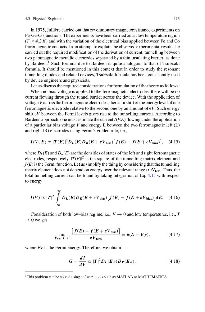
I(V , E) ∝ |T (E)|
2 D L (E) D R (E + eV bias )
f (E) − f (E + eV bias )
, (4.15)
where D L (E) and D R (E) are the densities of states of the left and right ferromagnetic
electrodes, respectively. |T (E)|
2 is the square of the tunnelling matrix element and
f (E) is the Fermi function. Let us simplify the thing by considering that the tunnelling
matrix element does not depend on energy over the relevant range ≈eV bias . Thus, the
total tunnelling current can be found by taking integration of Eq. 4.15 with respect
to energy
I(V ) ∝ |T |
2
∞
−∞
D L (E) D R (E + eV bias )
f (E) − f (E + eV bias )
d E. (4.16)
Consideration of both low-bias regime, i.e., V → 0 and low temperatures, i.e., T
→ 0 we get
lim
V bias ,T →0
f (E) − f (E + eV bias )
eV bias
= δ(E − E F ),
(4.17)
where E F is the Fermi energy. Therefore, we obtain
G =
d I
dV
∝ |T |
2 D L (E F ) D R (E F ),
(4.18)
1 This problem can be solved using software tools such as MATLAB or MATHEMATICA.
113
In 1975, Jullière carried out that revolutionary magnetoresistance experiments on
Fe-Ge-Co junctions. The experiments have been carried out at low temperature region
(T ≤ 4.2 K) and with the variation of the electrical bias applied between Fe and Co
ferromagnetic contacts. In an attempt to explain the observed experimental results, he
carried out the required modification of the derivation of current, tunnelling between
two paramagnetic metallic electrodes separated by a thin insulating barrier, as done
by Bardeen.
1 Such formula due to Bardeen is quite analogous to that of TsuEsaki
formula. It should be mentioned in this context that in order to study the resonant
tunnelling diodes and related devices, TsuEsaki formula has been consistently used
by device engineers and physicists.
Let us discuss the required considerations for formulation of the theory as follows:
When no bias voltage is applied to the ferromagnetic electrodes, there will be no
current flowing through the tunnel barrier across the device. With the application of
voltage V across the ferromagnetic electrodes, there is a shift of the energy level of one
ferromagnetic electrode relative to the second one by an amount of eV. Such energy
shift eV between the Fermi levels gives rise to the tunnelling current. According to
Bardeen approach, one must estimate the current I(V,E) flowing under the application
of a particular bias voltage V and energy E between the two ferromagnetic left (L)
and right (R) electrodes using Fermi’s golden rule, i.e.,
I(V , E) ∝ |T (E)|
2 D L (E) D R (E + eV bias )
f (E) − f (E + eV bias )
, (4.15)
where D L (E) and D R (E) are the densities of states of the left and right ferromagnetic
electrodes, respectively. |T (E)|
2 is the square of the tunnelling matrix element and
f (E) is the Fermi function. Let us simplify the thing by considering that the tunnelling
matrix element does not depend on energy over the relevant range ≈eV bias . Thus, the
total tunnelling current can be found by taking integration of Eq. 4.15 with respect
to energy
I(V ) ∝ |T |
2
∞
−∞
D L (E) D R (E + eV bias )
f (E) − f (E + eV bias )
d E. (4.16)
Consideration of both low-bias regime, i.e., V → 0 and low temperatures, i.e., T
→ 0 we get
lim
V bias ,T →0
f (E) − f (E + eV bias )
eV bias
= δ(E − E F ),
(4.17)
where E F is the Fermi energy. Therefore, we obtain
G =
d I
dV
∝ |T |
2 D L (E F ) D R (E F ),
(4.18)
1 This problem can be solved using software tools such as MATLAB or MATHEMATICA.