

inside the Linkam Scientific system controller unit. Place the
system controller unit to the left of the microscope.
3. Remove the four transit screws (and corresponding washers)
from the bottom of the Linkam Scientific liquid nitrogen pump
Cryomicroscope
System Controller
Liquid Nitrogen Pump
Dewar
Light Source
Computer
Monitor
Camera
Microscope
Trigger
Switch
Stage
Trigger Interface Cable
Stage Cable
Instrument
Bus Cable
Nitrogen Withdrawal
Tubing (and Return)
Insulated Capillary
Data Transfer Cable
Serial Communication
Cable
Data Archive
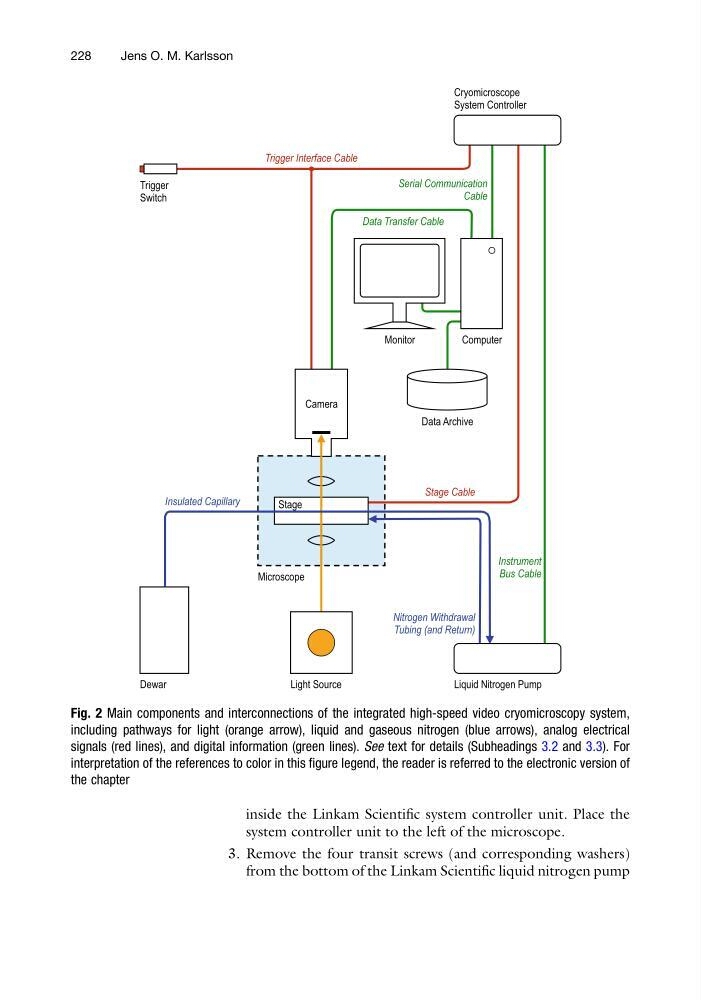
Fig. 2 Main components and interconnections of the integrated high-speed video cryomicroscopy system,
including pathways for light (orange arrow), liquid and gaseous nitrogen (blue arrows), analog electrical
signals (red lines), and digital information (green lines). See text for details (Subheadings 3.2 and 3.3). For
interpretation of the references to color in this figure legend, the reader is referred to the electronic version of
the chapter
228
Jens O. M. Karlsson
system controller unit to the left of the microscope.
3. Remove the four transit screws (and corresponding washers)
from the bottom of the Linkam Scientific liquid nitrogen pump
Cryomicroscope
System Controller
Liquid Nitrogen Pump
Dewar
Light Source
Computer
Monitor
Camera
Microscope
Trigger
Switch
Stage
Trigger Interface Cable
Stage Cable
Instrument
Bus Cable
Nitrogen Withdrawal
Tubing (and Return)
Insulated Capillary
Data Transfer Cable
Serial Communication
Cable
Data Archive
Fig. 2 Main components and interconnections of the integrated high-speed video cryomicroscopy system,
including pathways for light (orange arrow), liquid and gaseous nitrogen (blue arrows), analog electrical
signals (red lines), and digital information (green lines). See text for details (Subheadings 3.2 and 3.3). For
interpretation of the references to color in this figure legend, the reader is referred to the electronic version of
the chapter
228
Jens O. M. Karlsson