

202
5 Electrodynamics of Aqueous Media
Woisetschlager et al. found in addition [71] that the temperature of the bridge
increases with time and finally causes its collapse after about 45 min by the stability breakdown. The effect can be interpreted by means of the electrophoretic
retardation force, formed by the ions of the opposite signs, which moves in opposite
directions under the conditions of electrostatic interaction. Note that the ionic model
(see Sect. 4.2) assumes short-lived (picosecond) ionic species, with concentrations
up to 1 mol/l, which is high enough to (a) explain the fast mass transfer through the
water bridge observed in the experiment and (b) provide an additional electrostatic
restoring force when the ionic species become relatively displaced by the external
electric field (see below). The nanoscale density fluctuations inside the bridge (found
by Skinner et al. [62]) indirectly confirm the 1 nm spatial heterogeneity, which was
found in water by means of dielectric spectroscopy (see Chap. 4).
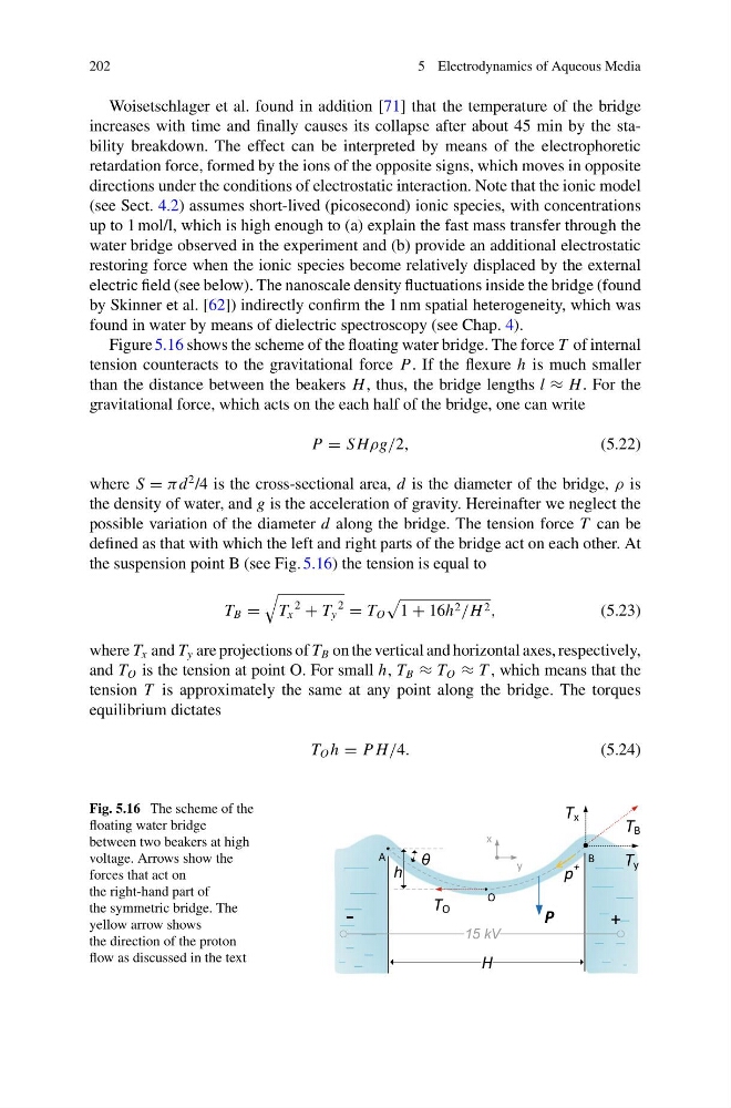
Figure 5.16 shows the scheme of the floating water bridge. The force T of internal
tension counteracts to the gravitational force P. If the flexure h is much smaller
than the distance between the beakers H , thus, the bridge lengths l ≈ H . For the
gravitational force, which acts on the each half of the bridge, one can write
P = S Hρg/2,
(5.22)
where S = π d
2 /4 is the cross-sectional area, d is the diameter of the bridge, ρ is
the density of water, and g is the acceleration of gravity. Hereinafter we neglect the
possible variation of the diameter d along the bridge. The tension force T can be
defined as that with which the left and right parts of the bridge act on each other. At
the suspension point B (see Fig. 5.16) the tension is equal to
T B =
T x
2
+ T y
2
= T O
1 + 16h 2 /H 2 ,
(5.23)
where T x and T y are projections of T B on the vertical and horizontal axes, respectively,
and T O is the tension at point O. For small h, T B ≈ T O ≈ T , which means that the
tension T is approximately the same at any point along the bridge. The torques
equilibrium dictates
T O h = P H/4.
(5.24)
Fig. 5.16 The scheme of the
floating water bridge
between two beakers at high
voltage. Arrows show the
forces that act on
the right-hand part of
the symmetric bridge. The
yellow arrow shows
the direction of the proton
flow as discussed in the text
P
H
θ
+
-
p
+
15 kV
A
B
h
T y
x
y
O
T O
T B
T x
5 Electrodynamics of Aqueous Media
Woisetschlager et al. found in addition [71] that the temperature of the bridge
increases with time and finally causes its collapse after about 45 min by the stability breakdown. The effect can be interpreted by means of the electrophoretic
retardation force, formed by the ions of the opposite signs, which moves in opposite
directions under the conditions of electrostatic interaction. Note that the ionic model
(see Sect. 4.2) assumes short-lived (picosecond) ionic species, with concentrations
up to 1 mol/l, which is high enough to (a) explain the fast mass transfer through the
water bridge observed in the experiment and (b) provide an additional electrostatic
restoring force when the ionic species become relatively displaced by the external
electric field (see below). The nanoscale density fluctuations inside the bridge (found
by Skinner et al. [62]) indirectly confirm the 1 nm spatial heterogeneity, which was
found in water by means of dielectric spectroscopy (see Chap. 4).
Figure 5.16 shows the scheme of the floating water bridge. The force T of internal
tension counteracts to the gravitational force P. If the flexure h is much smaller
than the distance between the beakers H , thus, the bridge lengths l ≈ H . For the
gravitational force, which acts on the each half of the bridge, one can write
P = S Hρg/2,
(5.22)
where S = π d
2 /4 is the cross-sectional area, d is the diameter of the bridge, ρ is
the density of water, and g is the acceleration of gravity. Hereinafter we neglect the
possible variation of the diameter d along the bridge. The tension force T can be
defined as that with which the left and right parts of the bridge act on each other. At
the suspension point B (see Fig. 5.16) the tension is equal to
T B =
T x
2
+ T y
2
= T O
1 + 16h 2 /H 2 ,
(5.23)
where T x and T y are projections of T B on the vertical and horizontal axes, respectively,
and T O is the tension at point O. For small h, T B ≈ T O ≈ T , which means that the
tension T is approximately the same at any point along the bridge. The torques
equilibrium dictates
T O h = P H/4.
(5.24)
Fig. 5.16 The scheme of the
floating water bridge
between two beakers at high
voltage. Arrows show the
forces that act on
the right-hand part of
the symmetric bridge. The
yellow arrow shows
the direction of the proton
flow as discussed in the text
P
H
θ
+
-
p
+
15 kV
A
B
h
T y
x
y
O
T O
T B
T x