

Ultrasound Imaging
329
In Figure 16.8, a state-of-the-art portable ultrasound imaging device manufactured
by Ardent Sound Therapy, Inc., Mesa, AZ, operating in reflection mode is shown.
Figure 16.9 shows the pulsating characteristics of flow, and the direction of flow is
exhibited by the deflection of the Doppler signal (positive or negative).
16.7 MODES OF ULTRASOUND IMAGE REPRESENTATION
Some of the main commercial modes of ultrasound imaging that are used in medical
imaging applications are B-mode, M-mode, and TM-modes. These imaging modes
are essentially the methods of showing the measures data in the form of images. In
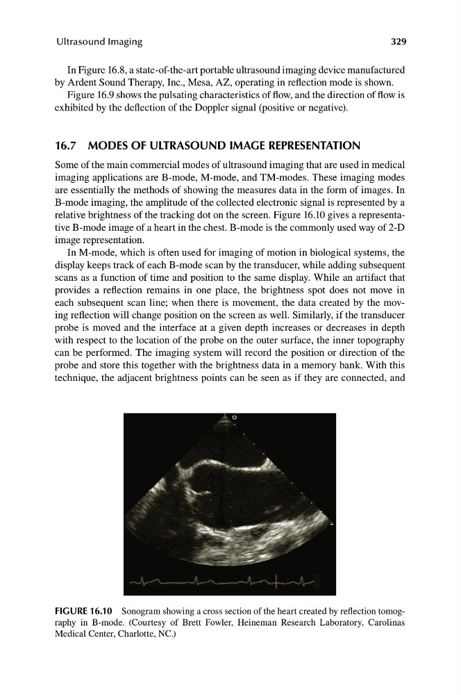
B-mode imaging, the amplitude of the collected electronic signal is represented by a
relative brightness of the tracking dot on the screen. Figure 16.10 gives a representative B-mode image of a heart in the chest. B-mode is the commonly used way of 2-D
image representation.
In M-mode, which is often used for imaging of motion in biological systems, the
display keeps track of each B-mode scan by the transducer, while adding subsequent
scans as a function of time and position to the same display. While an artifact that
provides a reflection remains in one place, the brightness spot does not move in
each subsequent scan line; when there is movement, the data created by the moving reflection will change position on the screen as well. Similarly, if the transducer
probe is moved and the interface at a given depth increases or decreases in depth
with respect to the location of the probe on the outer surface, the inner topography
can be performed. The imaging system will record the position or direction of the
probe and store this together with the brightness data in a memory bank. With this
technique, the adjacent brightness points can be seen as if they are connected, and
FIGURE 16.10 Sonogram showing a cross section of the heart created by reflection tomography in B-mode. (Courtesy of Brett Fowler, Heineman Research Laboratory, Carolinas
Medical Center, Charlotte, NC.)
329
In Figure 16.8, a state-of-the-art portable ultrasound imaging device manufactured
by Ardent Sound Therapy, Inc., Mesa, AZ, operating in reflection mode is shown.
Figure 16.9 shows the pulsating characteristics of flow, and the direction of flow is
exhibited by the deflection of the Doppler signal (positive or negative).
16.7 MODES OF ULTRASOUND IMAGE REPRESENTATION
Some of the main commercial modes of ultrasound imaging that are used in medical
imaging applications are B-mode, M-mode, and TM-modes. These imaging modes
are essentially the methods of showing the measures data in the form of images. In
B-mode imaging, the amplitude of the collected electronic signal is represented by a
relative brightness of the tracking dot on the screen. Figure 16.10 gives a representative B-mode image of a heart in the chest. B-mode is the commonly used way of 2-D
image representation.
In M-mode, which is often used for imaging of motion in biological systems, the
display keeps track of each B-mode scan by the transducer, while adding subsequent
scans as a function of time and position to the same display. While an artifact that
provides a reflection remains in one place, the brightness spot does not move in
each subsequent scan line; when there is movement, the data created by the moving reflection will change position on the screen as well. Similarly, if the transducer
probe is moved and the interface at a given depth increases or decreases in depth
with respect to the location of the probe on the outer surface, the inner topography
can be performed. The imaging system will record the position or direction of the
probe and store this together with the brightness data in a memory bank. With this
technique, the adjacent brightness points can be seen as if they are connected, and
FIGURE 16.10 Sonogram showing a cross section of the heart created by reflection tomography in B-mode. (Courtesy of Brett Fowler, Heineman Research Laboratory, Carolinas
Medical Center, Charlotte, NC.)