

p(t)
ψ(t)
Tissue
Electric
pulse generator
and receiver
p(t)
p 1 (t) z 1 (t)
ψ(t) ψ 1 (t)
x
(a)
(b)
325
Ultrasound Imaging
Equation 16.35 is the tomographic equation that allows forming images of the biological systems based on different speeds of sound waves in different biological tissues. Note that t d and l w are measured, and β w (f) is known for all frequencies. Taking
several such measurements in several directions provides the measurements for solving the previous tomographic equation.
As mentioned earlier, in some cases, the line of sight access to the biological
organs to be imaged may not be possible. In such cases, neither attenuation tomography nor the TOF tomography that requires the transmitter and receiver on different
sides of the object may be a suitable solution. For such very important imaging scenario, ultrasound reflection tomography, as introduced later, is used.
16.6.3 REFLECTION TOMOGRAPHY
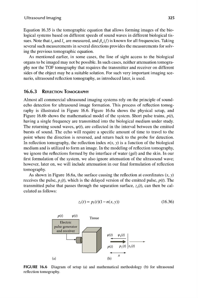
Almost all commercial ultrasound imaging systems rely on the principle of soundecho detection for ultrasound image formation. This process of reflection tomography is illustrated in Figure 16.6. Figure 16.6a shows the physical setup, and
Figure 16.6b shows the mathematical model of the system. Short pulse trains, p(t),
having a single frequency are transmitted into the biological medium under study.
The returning sound waves, ψ(t), are collected in the interval between the emitted
bursts of sound. The echo will require a specific amount of time to travel to the
point where the direction is reversed, and return back to the probe for detection.
In reflection tomography, the reflection index n(x, y) is a function of the biological
medium and is utilized to form an image. In the modeling of reflection tomography,
we ignore the reflections formed by the interface of water (gel) and the skin. In our
first formulation of the system, we also ignore attenuation of the ultrasound wave;
however, later on, we will include attenuation in our final formulation of reflection
tomography.
As shown in Figure 16.6a, the surface causing the reflection at coordinates (x, y)
receives the pulse, p 1 (t), which is the delayed version of the emitted pulse, p(t). The
transmitted pulse that passes through the separation surface, z 1 (t), can then be calculated as follows:
z t = p t 1 − n(x y ))
1 ( )
1 ( )(
,
(16.36)
FIGURE 16.6 Diagram of setup (a) and mathematical methodology (b) for ultrasound
reflection tomography.
ψ(t)
Tissue
Electric
pulse generator
and receiver
p(t)
p 1 (t) z 1 (t)
ψ(t) ψ 1 (t)
x
(a)
(b)
325
Ultrasound Imaging
Equation 16.35 is the tomographic equation that allows forming images of the biological systems based on different speeds of sound waves in different biological tissues. Note that t d and l w are measured, and β w (f) is known for all frequencies. Taking
several such measurements in several directions provides the measurements for solving the previous tomographic equation.
As mentioned earlier, in some cases, the line of sight access to the biological
organs to be imaged may not be possible. In such cases, neither attenuation tomography nor the TOF tomography that requires the transmitter and receiver on different
sides of the object may be a suitable solution. For such very important imaging scenario, ultrasound reflection tomography, as introduced later, is used.
16.6.3 REFLECTION TOMOGRAPHY
Almost all commercial ultrasound imaging systems rely on the principle of soundecho detection for ultrasound image formation. This process of reflection tomography is illustrated in Figure 16.6. Figure 16.6a shows the physical setup, and
Figure 16.6b shows the mathematical model of the system. Short pulse trains, p(t),
having a single frequency are transmitted into the biological medium under study.
The returning sound waves, ψ(t), are collected in the interval between the emitted
bursts of sound. The echo will require a specific amount of time to travel to the
point where the direction is reversed, and return back to the probe for detection.
In reflection tomography, the reflection index n(x, y) is a function of the biological
medium and is utilized to form an image. In the modeling of reflection tomography,
we ignore the reflections formed by the interface of water (gel) and the skin. In our
first formulation of the system, we also ignore attenuation of the ultrasound wave;
however, later on, we will include attenuation in our final formulation of reflection
tomography.
As shown in Figure 16.6a, the surface causing the reflection at coordinates (x, y)
receives the pulse, p 1 (t), which is the delayed version of the emitted pulse, p(t). The
transmitted pulse that passes through the separation surface, z 1 (t), can then be calculated as follows:
z t = p t 1 − n(x y ))
1 ( )
1 ( )(
,
(16.36)
FIGURE 16.6 Diagram of setup (a) and mathematical methodology (b) for ultrasound
reflection tomography.