

180
Biomedical Signal and Image Processing
In general, all electric recordings are made in differential amplifier mode. In
differential amplification, the electric potential difference signal measured between
two points is amplified, and, therefore, the common signal components that will
be recorded on both electrodes simultaneously will be filtered out. This process
is called common-mode rejection. Since various noise sources will have an identical impact on the recorded electric activity on electrodes, by measuring the difference between the electrodes, i.e., common-mode rejection, the noise is simply
eliminated.
In general, the 12 recording protocol is the standard mode of operation. However,
other minimally invasive electrode placement techniques involve the use of a springloaded catheter placed inside the left ventricle with multiple strands of electrode
wires. Each strand can have 16 electrodes, and there can be 16 strands deployed.
These strands will press against the endocardial wall and record an array of simultaneous measurements in close proximity to the depolarizing cells. This type of
measurement is usually reserved for research purposes and for cases that are difficult
to diagnose by standard procedures.
More accurate measurements can be made with the help of coronary electrode
placement and ventricular electrode placement through insertion of a catheter
equipped with electrodes. Most catheters have two or three electrodes on a single
catheter, and several catheters can be inserted simultaneously.
9.3.3 MODELING AND REPRESENTATION OF ECG
Einthoven introduced the concept that electric activity of the heart can be described
by a single current dipole with a resulting three-dimensional (3-D) rotating field
vector, called the heart vector. The concept of the heart vector is illustrated in
Figure 9.7, where all the recordings at a 120° angle difference with each other are
combined to give the geometrical projection in one resultant direction. The heart
vector represents the magnitude and the direction of the dipole moment caused by
the current dipole, which is the cumulative polarization and repolarization ion flow
across the cardiac cells.
The main postulate in the forming and analysis of the heart vectors is that the
electric activity of the heart at any time can be described by the heart vector. In
order to provide a geometry that simplifies the calculations of the heart vector, the
human body is considered as a sphere with the source of the heart vector located at
the center. In this geometry, even though the two arms and the left leg all protrude
from the sphere, they are assumed to be in one plane and at equal distances from the
center. In forming the heart vectors, it is also assumed that the electric conduction is
homogeneous and isotropic over the sphere.
At first glance, it seems that each of the arm and leg recordings I, II, and II
described for the Einthoven placement contributes some additional information on
the magnitude and direction of the heart vector. However, the three recordings are
not truly independent, since applying Kirchhoff rule gives
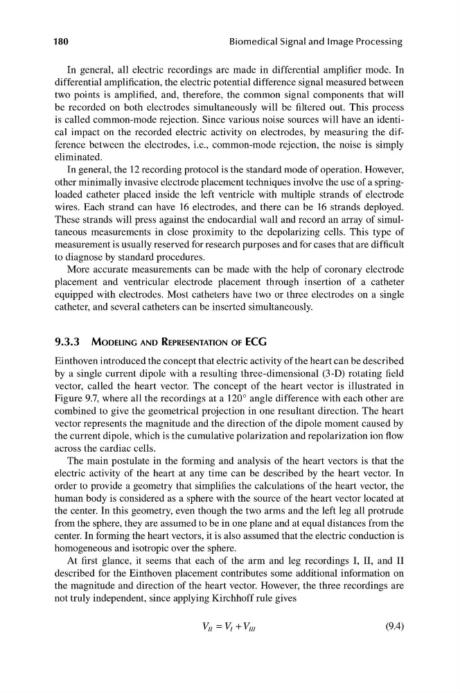
V II = V I + V III
(9.4)
Biomedical Signal and Image Processing
In general, all electric recordings are made in differential amplifier mode. In
differential amplification, the electric potential difference signal measured between
two points is amplified, and, therefore, the common signal components that will
be recorded on both electrodes simultaneously will be filtered out. This process
is called common-mode rejection. Since various noise sources will have an identical impact on the recorded electric activity on electrodes, by measuring the difference between the electrodes, i.e., common-mode rejection, the noise is simply
eliminated.
In general, the 12 recording protocol is the standard mode of operation. However,
other minimally invasive electrode placement techniques involve the use of a springloaded catheter placed inside the left ventricle with multiple strands of electrode
wires. Each strand can have 16 electrodes, and there can be 16 strands deployed.
These strands will press against the endocardial wall and record an array of simultaneous measurements in close proximity to the depolarizing cells. This type of
measurement is usually reserved for research purposes and for cases that are difficult
to diagnose by standard procedures.
More accurate measurements can be made with the help of coronary electrode
placement and ventricular electrode placement through insertion of a catheter
equipped with electrodes. Most catheters have two or three electrodes on a single
catheter, and several catheters can be inserted simultaneously.
9.3.3 MODELING AND REPRESENTATION OF ECG
Einthoven introduced the concept that electric activity of the heart can be described
by a single current dipole with a resulting three-dimensional (3-D) rotating field
vector, called the heart vector. The concept of the heart vector is illustrated in
Figure 9.7, where all the recordings at a 120° angle difference with each other are
combined to give the geometrical projection in one resultant direction. The heart
vector represents the magnitude and the direction of the dipole moment caused by
the current dipole, which is the cumulative polarization and repolarization ion flow
across the cardiac cells.
The main postulate in the forming and analysis of the heart vectors is that the
electric activity of the heart at any time can be described by the heart vector. In
order to provide a geometry that simplifies the calculations of the heart vector, the
human body is considered as a sphere with the source of the heart vector located at
the center. In this geometry, even though the two arms and the left leg all protrude
from the sphere, they are assumed to be in one plane and at equal distances from the
center. In forming the heart vectors, it is also assumed that the electric conduction is
homogeneous and isotropic over the sphere.
At first glance, it seems that each of the arm and leg recordings I, II, and II
described for the Einthoven placement contributes some additional information on
the magnitude and direction of the heart vector. However, the three recordings are
not truly independent, since applying Kirchhoff rule gives
V II = V I + V III
(9.4)