

inside the enclosure. By means of the particle image velocimetry (PIV) technique
(Raffel et al. 1998; Sveen and Cowen 2004) measurements of the velocity field very
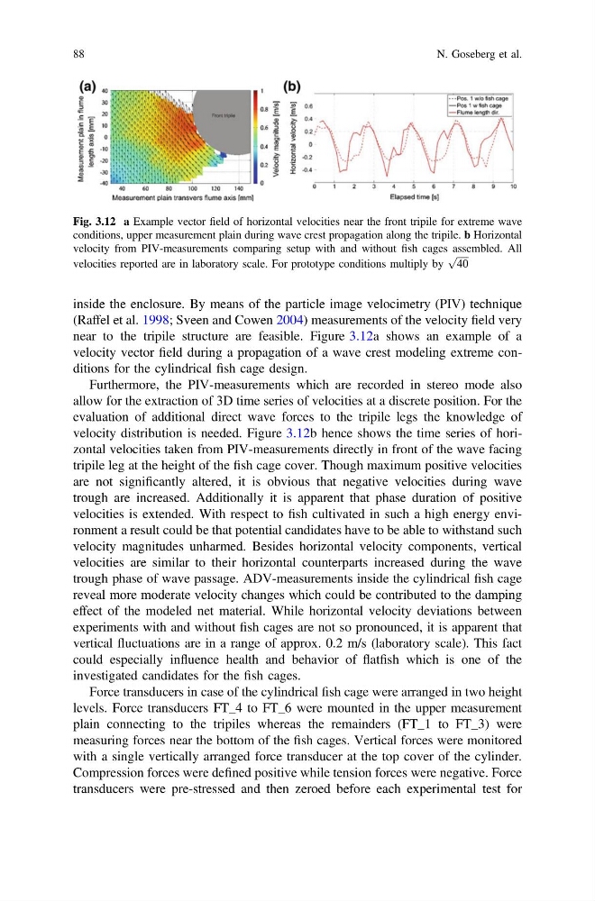
near to the tripile structure are feasible. Figure 3.12a shows an example of a
velocity vector field during a propagation of a wave crest modeling extreme conditions for the cylindrical fish cage design.
Furthermore, the PIV-measurements which are recorded in stereo mode also
allow for the extraction of 3D time series of velocities at a discrete position. For the
evaluation of additional direct wave forces to the tripile legs the knowledge of
velocity distribution is needed. Figure 3.12b hence shows the time series of horizontal velocities taken from PIV-measurements directly in front of the wave facing
tripile leg at the height of the fish cage cover. Though maximum positive velocities
are not significantly altered, it is obvious that negative velocities during wave
trough are increased. Additionally it is apparent that phase duration of positive
velocities is extended. With respect to fish cultivated in such a high energy environment a result could be that potential candidates have to be able to withstand such
velocity magnitudes unharmed. Besides horizontal velocity components, vertical
velocities are similar to their horizontal counterparts increased during the wave
trough phase of wave passage. ADV-measurements inside the cylindrical fish cage
reveal more moderate velocity changes which could be contributed to the damping
effect of the modeled net material. While horizontal velocity deviations between
experiments with and without fish cages are not so pronounced, it is apparent that
vertical fluctuations are in a range of approx. 0.2 m/s (laboratory scale). This fact
could especially influence health and behavior of flatfish which is one of the
investigated candidates for the fish cages.
Force transducers in case of the cylindrical fish cage were arranged in two height
levels. Force transducers FT_4 to FT_6 were mounted in the upper measurement
plain connecting to the tripiles whereas the remainders (FT_1 to FT_3) were
measuring forces near the bottom of the fish cages. Vertical forces were monitored
with a single vertically arranged force transducer at the top cover of the cylinder.
Compression forces were defined positive while tension forces were negative. Force
transducers were pre-stressed and then zeroed before each experimental test for
Fig. 3.12 a Example vector field of horizontal velocities near the front tripile for extreme wave
conditions, upper measurement plain during wave crest propagation along the tripile. b Horizontal
velocity from PIV-measurements comparing setup with and without fish cages assembled. All
velocities reported are in laboratory scale. For prototype conditions multiply by
ffiffiffiffiffi
40
p
88
N. Goseberg et al.
(Raffel et al. 1998; Sveen and Cowen 2004) measurements of the velocity field very
near to the tripile structure are feasible. Figure 3.12a shows an example of a
velocity vector field during a propagation of a wave crest modeling extreme conditions for the cylindrical fish cage design.
Furthermore, the PIV-measurements which are recorded in stereo mode also
allow for the extraction of 3D time series of velocities at a discrete position. For the
evaluation of additional direct wave forces to the tripile legs the knowledge of
velocity distribution is needed. Figure 3.12b hence shows the time series of horizontal velocities taken from PIV-measurements directly in front of the wave facing
tripile leg at the height of the fish cage cover. Though maximum positive velocities
are not significantly altered, it is obvious that negative velocities during wave
trough are increased. Additionally it is apparent that phase duration of positive
velocities is extended. With respect to fish cultivated in such a high energy environment a result could be that potential candidates have to be able to withstand such
velocity magnitudes unharmed. Besides horizontal velocity components, vertical
velocities are similar to their horizontal counterparts increased during the wave
trough phase of wave passage. ADV-measurements inside the cylindrical fish cage
reveal more moderate velocity changes which could be contributed to the damping
effect of the modeled net material. While horizontal velocity deviations between
experiments with and without fish cages are not so pronounced, it is apparent that
vertical fluctuations are in a range of approx. 0.2 m/s (laboratory scale). This fact
could especially influence health and behavior of flatfish which is one of the
investigated candidates for the fish cages.
Force transducers in case of the cylindrical fish cage were arranged in two height
levels. Force transducers FT_4 to FT_6 were mounted in the upper measurement
plain connecting to the tripiles whereas the remainders (FT_1 to FT_3) were
measuring forces near the bottom of the fish cages. Vertical forces were monitored
with a single vertically arranged force transducer at the top cover of the cylinder.
Compression forces were defined positive while tension forces were negative. Force
transducers were pre-stressed and then zeroed before each experimental test for
Fig. 3.12 a Example vector field of horizontal velocities near the front tripile for extreme wave
conditions, upper measurement plain during wave crest propagation along the tripile. b Horizontal
velocity from PIV-measurements comparing setup with and without fish cages assembled. All
velocities reported are in laboratory scale. For prototype conditions multiply by
ffiffiffiffiffi
40
p
88
N. Goseberg et al.