

2.3 Design Requirements
17
Front-end Card
Common
Readout
Unit (CRU)
Detector
Data Links
(DDL3)
Local
Trigger
Unit (LTU)
Detector
Control
System
(DCS)
Timing and Trigger
distribution System (TTS)
Cavern
Control
room
Online
farm
Front-end
links (GBT)
Physics &
monitoring data
Trigger, control
and configuration
Physics data
Monitoring data
Control and
configuration
GBT-SCA
GBTx
(2x)
VTTx
VTRx
SAMPA (5x)
32 channels
160 input
channels
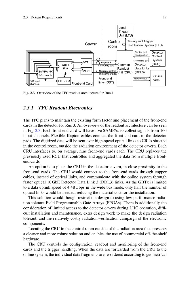
Fig. 2.3 Overview of the TPC readout architecture for Run 3
2.3.1 TPC Readout Electronics
The TPC plans to maintain the existing form factor and placement of the front-end
cards in the detector for Run 3. An overview of the readout architecture can be seen
in Fig. 2.3. Each front-end card will have five SAMPAs to collect signals from 160
input channels. Flexible Kapton cables connect the front-end card to the detector
pads. The digitized data will be sent over high-speed optical links to CRUs situated
in the control room, outside the radiation environment of the detector cavern. Each
CRU interfaces to, on average, nine front-end cards each. The CRU replaces the
previously used RCU that controlled and aggregated the data from multiple frontend cards.
An option is to place the CRU in the detector cavern, in close proximity to the
front-end cards. The CRU would connect to the front-end cards through copper
cables, instead of optical links, and communicate with the online system through
faster optical 10 GbE Detector Data Link 3 (DDL3) links. As the GBTx is limited
to a data uplink speed of 4.48 Gbps in the wide bus mode, only half the number of
optical links would be needed, reducing the material cost for the installation.
This solution would though restrict the design to using low performance radiation tolerant Field Programmable Gate Arrays (FPGAs). There is additionally the
consideration of limited access to the detector cavern during LHC operation, difficult installation and maintenance, extra design work to make the design radiation
tolerant, and the relatively costly radiation-verification campaign of the electronic
components.
Locating the CRU in the control room outside of the radiation area thus presents
a cleaner and more robust solution and enables the use of commercial off-the-shelf
hardware.
The CRU controls the configuration, readout and monitoring of the front-end
cards and the trigger handling. When the data are forwarded from the CRU to the
online system, the individual data fragments are re-ordered according to geometrical
17
Front-end Card
Common
Readout
Unit (CRU)
Detector
Data Links
(DDL3)
Local
Trigger
Unit (LTU)
Detector
Control
System
(DCS)
Timing and Trigger
distribution System (TTS)
Cavern
Control
room
Online
farm
Front-end
links (GBT)
Physics &
monitoring data
Trigger, control
and configuration
Physics data
Monitoring data
Control and
configuration
GBT-SCA
GBTx
(2x)
VTTx
VTRx
SAMPA (5x)
32 channels
160 input
channels
Fig. 2.3 Overview of the TPC readout architecture for Run 3
2.3.1 TPC Readout Electronics
The TPC plans to maintain the existing form factor and placement of the front-end
cards in the detector for Run 3. An overview of the readout architecture can be seen
in Fig. 2.3. Each front-end card will have five SAMPAs to collect signals from 160
input channels. Flexible Kapton cables connect the front-end card to the detector
pads. The digitized data will be sent over high-speed optical links to CRUs situated
in the control room, outside the radiation environment of the detector cavern. Each
CRU interfaces to, on average, nine front-end cards each. The CRU replaces the
previously used RCU that controlled and aggregated the data from multiple frontend cards.
An option is to place the CRU in the detector cavern, in close proximity to the
front-end cards. The CRU would connect to the front-end cards through copper
cables, instead of optical links, and communicate with the online system through
faster optical 10 GbE Detector Data Link 3 (DDL3) links. As the GBTx is limited
to a data uplink speed of 4.48 Gbps in the wide bus mode, only half the number of
optical links would be needed, reducing the material cost for the installation.
This solution would though restrict the design to using low performance radiation tolerant Field Programmable Gate Arrays (FPGAs). There is additionally the
consideration of limited access to the detector cavern during LHC operation, difficult installation and maintenance, extra design work to make the design radiation
tolerant, and the relatively costly radiation-verification campaign of the electronic
components.
Locating the CRU in the control room outside of the radiation area thus presents
a cleaner and more robust solution and enables the use of commercial off-the-shelf
hardware.
The CRU controls the configuration, readout and monitoring of the front-end
cards and the trigger handling. When the data are forwarded from the CRU to the
online system, the individual data fragments are re-ordered according to geometrical