

1.1 The ALICE Experiment
5
Absorber
Tracking
chambers
Magnet
Filter
Trigger
chamber
1
2
3
4
5
Fig. 1.4 Schematic overview of the Muon Spectrometer showing the absorber, the five tracking
chambers, the bending magnet, the muon filter, the trigger chambers, and two particle trajectories
DETECTOR
Front End Card - 128 CHANNELS
L 2 < 100 µs
200 Hz
8 CHIPS
x
16 CH / CHIP
8 CHIPS
x
16 CH / CHIP
L 1 6.5 µs
200 Hz
Drift region
100 µs
570132 pads
Pad
plane
CUSTOM IC
(CMOS 0.35µm)
CUSTOM IC (CMOS 0.25µm)
Gating grid
PASA
ADC
RAM
ALTRO chip
Data
Processor
MULTIEVENT
MEMORY
BASELINE CORR.
TAIL CANCELL.
ZERO SUPPR.
10 bit
10 MS/s
CHARGE SENS. AMPL.
SEMI-GAUSS. SHAPER
GAIN = 12 mV / fC
FWHM = 190 ns
Power
consumption:
< 100 mW / channel
1 MIP = 4.8 fC
S/N = 30:1
DYNAMIC = 30 MIP
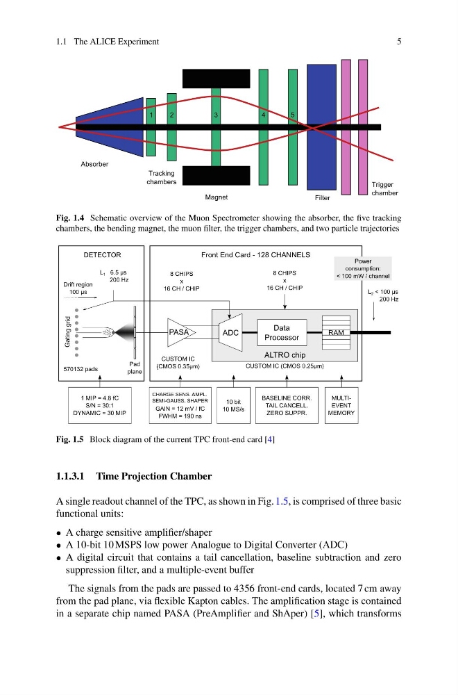
Fig. 1.5 Block diagram of the current TPC front-end card [4]
1.1.3.1 Time Projection Chamber
A single readout channel of the TPC, as shown in Fig. 1.5, is comprised of three basic
functional units:
• A charge sensitive amplifier/shaper
• A 10-bit 10 MSPS low power Analogue to Digital Converter (ADC)
• A digital circuit that contains a tail cancellation, baseline subtraction and zero
suppression filter, and a multiple-event buffer
The signals from the pads are passed to 4356 front-end cards, located 7 cm away
from the pad plane, via flexible Kapton cables. The amplification stage is contained
in a separate chip named PASA (PreAmplifier and ShAper) [5], which transforms
5
Absorber
Tracking
chambers
Magnet
Filter
Trigger
chamber
1
2
3
4
5
Fig. 1.4 Schematic overview of the Muon Spectrometer showing the absorber, the five tracking
chambers, the bending magnet, the muon filter, the trigger chambers, and two particle trajectories
DETECTOR
Front End Card - 128 CHANNELS
L 2 < 100 µs
200 Hz
8 CHIPS
x
16 CH / CHIP
8 CHIPS
x
16 CH / CHIP
L 1 6.5 µs
200 Hz
Drift region
100 µs
570132 pads
Pad
plane
CUSTOM IC
(CMOS 0.35µm)
CUSTOM IC (CMOS 0.25µm)
Gating grid
PASA
ADC
RAM
ALTRO chip
Data
Processor
MULTIEVENT
MEMORY
BASELINE CORR.
TAIL CANCELL.
ZERO SUPPR.
10 bit
10 MS/s
CHARGE SENS. AMPL.
SEMI-GAUSS. SHAPER
GAIN = 12 mV / fC
FWHM = 190 ns
Power
consumption:
< 100 mW / channel
1 MIP = 4.8 fC
S/N = 30:1
DYNAMIC = 30 MIP
Fig. 1.5 Block diagram of the current TPC front-end card [4]
1.1.3.1 Time Projection Chamber
A single readout channel of the TPC, as shown in Fig. 1.5, is comprised of three basic
functional units:
• A charge sensitive amplifier/shaper
• A 10-bit 10 MSPS low power Analogue to Digital Converter (ADC)
• A digital circuit that contains a tail cancellation, baseline subtraction and zero
suppression filter, and a multiple-event buffer
The signals from the pads are passed to 4356 front-end cards, located 7 cm away
from the pad plane, via flexible Kapton cables. The amplification stage is contained
in a separate chip named PASA (PreAmplifier and ShAper) [5], which transforms