

4.1 Functional Verification of the Digital Design
97
4.1.2 Module Based Testbenches
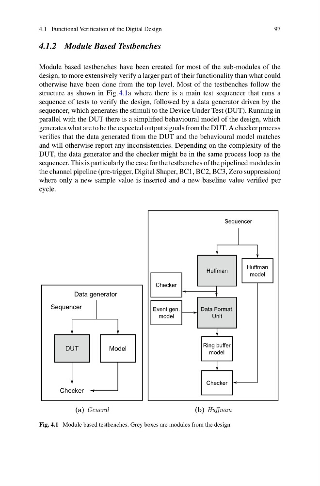
Module based testbenches have been created for most of the sub-modules of the
design, to more extensively verify a larger part of their functionality than what could
otherwise have been done from the top level. Most of the testbenches follow the
structure as shown in Fig. 4.1a where there is a main test sequencer that runs a
sequence of tests to verify the design, followed by a data generator driven by the
sequencer, which generates the stimuli to the Device Under Test (DUT). Running in
parallel with the DUT there is a simplified behavioural model of the design, which
generates what are to be the expected output signals from the DUT. A checker process
verifies that the data generated from the DUT and the behavioural model matches
and will otherwise report any inconsistencies. Depending on the complexity of the
DUT, the data generator and the checker might be in the same process loop as the
sequencer. This is particularly the case for the testbenches of the pipelined modules in
the channel pipeline (pre-trigger, Digital Shaper, BC1, BC2, BC3, Zero suppression)
where only a new sample value is inserted and a new baseline value verified per
cycle.
DUT
Model
Sequencer
Checker
Data generator
(a) General
Huffman
Data Format.
Unit
Huffman
model
Ring buffer
model
Sequencer
Checker
Event gen.
model
Checker
(b) Huffman
Fig. 4.1 Module based testbenches. Grey boxes are modules from the design
97
4.1.2 Module Based Testbenches
Module based testbenches have been created for most of the sub-modules of the
design, to more extensively verify a larger part of their functionality than what could
otherwise have been done from the top level. Most of the testbenches follow the
structure as shown in Fig. 4.1a where there is a main test sequencer that runs a
sequence of tests to verify the design, followed by a data generator driven by the
sequencer, which generates the stimuli to the Device Under Test (DUT). Running in
parallel with the DUT there is a simplified behavioural model of the design, which
generates what are to be the expected output signals from the DUT. A checker process
verifies that the data generated from the DUT and the behavioural model matches
and will otherwise report any inconsistencies. Depending on the complexity of the
DUT, the data generator and the checker might be in the same process loop as the
sequencer. This is particularly the case for the testbenches of the pipelined modules in
the channel pipeline (pre-trigger, Digital Shaper, BC1, BC2, BC3, Zero suppression)
where only a new sample value is inserted and a new baseline value verified per
cycle.
DUT
Model
Sequencer
Checker
Data generator
(a) General
Huffman
Data Format.
Unit
Huffman
model
Ring buffer
model
Sequencer
Checker
Event gen.
model
Checker
(b) Huffman
Fig. 4.1 Module based testbenches. Grey boxes are modules from the design