

78
3 Applications of Zero-Index Metamaterials
(a)
(b)
Incident beam
Reflected beam
(c)
Incident beam
Reflected beam
(d)
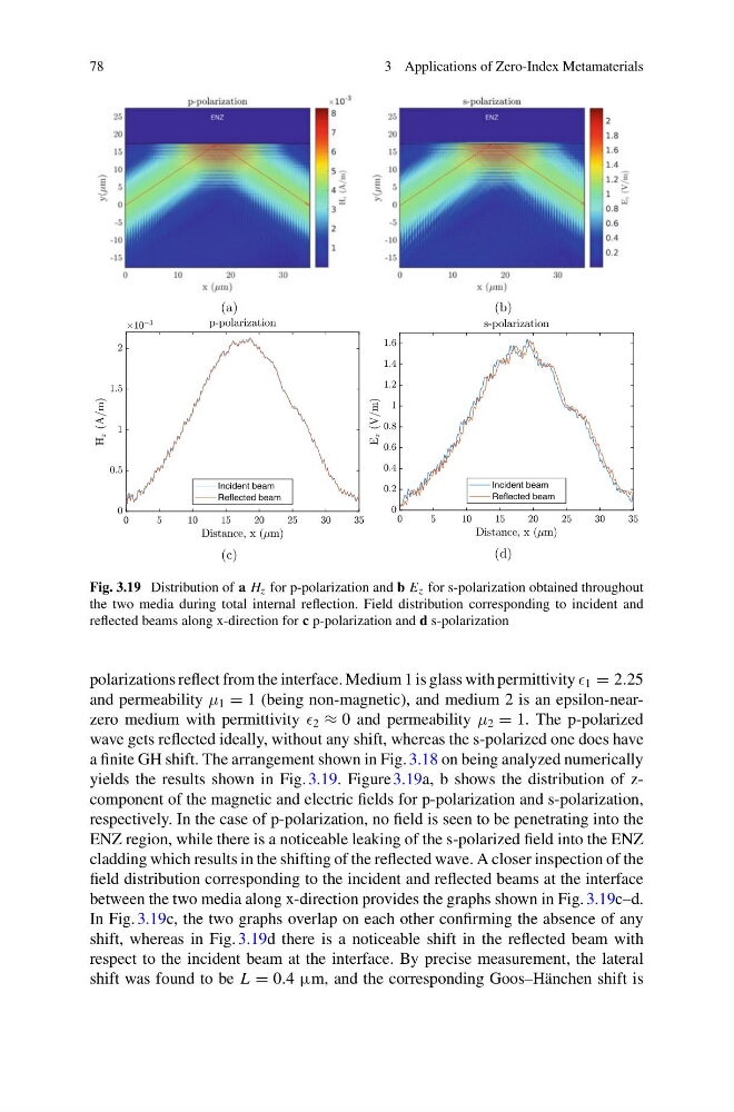
Fig. 3.19 Distribution of a H z for p-polarization and b E z for s-polarization obtained throughout
the two media during total internal reflection. Field distribution corresponding to incident and
reflected beams along x-direction for c p-polarization and d s-polarization
polarizations reflect from the interface. Medium 1 is glass with permittivity 1 = 2.25
and permeability μ 1 = 1 (being non-magnetic), and medium 2 is an epsilon-nearzero medium with permittivity 2 ≈ 0 and permeability μ 2 = 1. The p-polarized
wave gets reflected ideally, without any shift, whereas the s-polarized one does have
a finite GH shift. The arrangement shown in Fig. 3.18 on being analyzed numerically
yields the results shown in Fig. 3.19. Figure 3.19a, b shows the distribution of zcomponent of the magnetic and electric fields for p-polarization and s-polarization,
respectively. In the case of p-polarization, no field is seen to be penetrating into the
ENZ region, while there is a noticeable leaking of the s-polarized field into the ENZ
cladding which results in the shifting of the reflected wave. A closer inspection of the
field distribution corresponding to the incident and reflected beams at the interface
between the two media along x-direction provides the graphs shown in Fig. 3.19c–d.
In Fig. 3.19c, the two graphs overlap on each other confirming the absence of any
shift, whereas in Fig. 3.19d there is a noticeable shift in the reflected beam with
respect to the incident beam at the interface. By precise measurement, the lateral
shift was found to be L = 0.4 µm, and the corresponding Goos–Hänchen shift is
3 Applications of Zero-Index Metamaterials
(a)
(b)
Incident beam
Reflected beam
(c)
Incident beam
Reflected beam
(d)
Fig. 3.19 Distribution of a H z for p-polarization and b E z for s-polarization obtained throughout
the two media during total internal reflection. Field distribution corresponding to incident and
reflected beams along x-direction for c p-polarization and d s-polarization
polarizations reflect from the interface. Medium 1 is glass with permittivity 1 = 2.25
and permeability μ 1 = 1 (being non-magnetic), and medium 2 is an epsilon-nearzero medium with permittivity 2 ≈ 0 and permeability μ 2 = 1. The p-polarized
wave gets reflected ideally, without any shift, whereas the s-polarized one does have
a finite GH shift. The arrangement shown in Fig. 3.18 on being analyzed numerically
yields the results shown in Fig. 3.19. Figure 3.19a, b shows the distribution of zcomponent of the magnetic and electric fields for p-polarization and s-polarization,
respectively. In the case of p-polarization, no field is seen to be penetrating into the
ENZ region, while there is a noticeable leaking of the s-polarized field into the ENZ
cladding which results in the shifting of the reflected wave. A closer inspection of the
field distribution corresponding to the incident and reflected beams at the interface
between the two media along x-direction provides the graphs shown in Fig. 3.19c–d.
In Fig. 3.19c, the two graphs overlap on each other confirming the absence of any
shift, whereas in Fig. 3.19d there is a noticeable shift in the reflected beam with
respect to the incident beam at the interface. By precise measurement, the lateral
shift was found to be L = 0.4 µm, and the corresponding Goos–Hänchen shift is