

5.4 Zero-Index-Metamaterial-Based Nanoantenna
125
-150
-100
-50
50
100
150
Azimuthal angle, (degrees)
-30
-25
-20
-15
-10
-5
5
Directivity, D (dB)
H plane
(a)
H plane
2
4
6
8
30
210
60
240
90
270
120
300
150
330
0
0
8
1
(b)
-150
-100
-50
50
100
150
polar angle, (degrees)
-25
-20
-15
-10
-5
5
Directivity, D (dB)
E plane
(c)
E plane
1
2
3
4
5
30
210
60
240
90
270
120
300
150
330
0
0
8
1
(d)
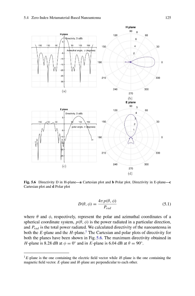
Fig. 5.6 Directivity D in H-plane—a Cartesian plot and b Polar plot. Directivity in E-plane—c
Cartesian plot and d Polar plot
D(θ, φ) =
4π p(θ, φ)
P rad
(5.1)
where θ and φ, respectively, represent the polar and azimuthal coordinates of a
spherical coordinate system, p(θ, φ) is the power radiated in a particular direction,
and P rad is the total power radiated. We calculated directivity of the nanoantenna in
both the E-plane and the H -plane.
1 The Cartesian and polar plots of directivity for
both the planes have been shown in Fig. 5.6. The maximum directivity obtained in
H -plane is 8.28 dB at φ = 0
◦ and in E-plane is 6.04 dB at θ = 90
◦ .
1 E-plane is the one containing the electric field vector while H -plane is the one containing the
magnetic field vector. E-plane and H -plane are perpendicular to each other.
125
-150
-100
-50
50
100
150
Azimuthal angle, (degrees)
-30
-25
-20
-15
-10
-5
5
Directivity, D (dB)
H plane
(a)
H plane
2
4
6
8
30
210
60
240
90
270
120
300
150
330
0
0
8
1
(b)
-150
-100
-50
50
100
150
polar angle, (degrees)
-25
-20
-15
-10
-5
5
Directivity, D (dB)
E plane
(c)
E plane
1
2
3
4
5
30
210
60
240
90
270
120
300
150
330
0
0
8
1
(d)
Fig. 5.6 Directivity D in H-plane—a Cartesian plot and b Polar plot. Directivity in E-plane—c
Cartesian plot and d Polar plot
D(θ, φ) =
4π p(θ, φ)
P rad
(5.1)
where θ and φ, respectively, represent the polar and azimuthal coordinates of a
spherical coordinate system, p(θ, φ) is the power radiated in a particular direction,
and P rad is the total power radiated. We calculated directivity of the nanoantenna in
both the E-plane and the H -plane.
1 The Cartesian and polar plots of directivity for
both the planes have been shown in Fig. 5.6. The maximum directivity obtained in
H -plane is 8.28 dB at φ = 0
◦ and in E-plane is 6.04 dB at θ = 90
◦ .
1 E-plane is the one containing the electric field vector while H -plane is the one containing the
magnetic field vector. E-plane and H -plane are perpendicular to each other.