

one thing in common – the particles carry only charges of one sign; therefore, they
repel each other. In range II, particles carry positive or negative charges; hence,
particles carrying charges with different sign attract each other. This leads to
additional agglomeration. Particles with a narrow size distribution may be obtained
only in cases of extreme short residence times in the reaction zone and efficient
quenching processes after the reaction zone.
The layout of a microwave plasma system, working in range I, for nanoparticle
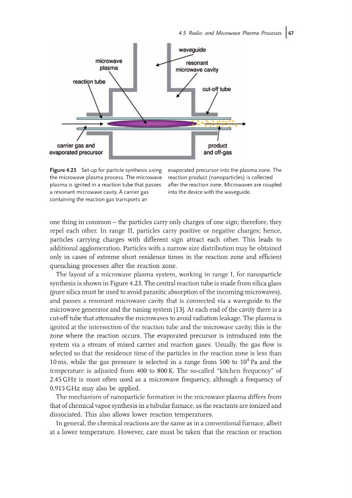
synthesis is shown in Figure 4.23. The central reaction tube is made from silica glass
(pure silica must be used to avoid parasitic absorption of the incoming microwaves),
and passes a resonant microwave cavity that is connected via a waveguide to the
microwave generator and the tuning system [13]. At each end of the cavity there is a
cut-off tube that attenuates the microwaves to avoid radiation leakage. The plasma is
ignited at the intersection of the reaction tube and the microwave cavity; this is the
zone where the reaction occurs. The evaporated precursor is introduced into the
system via a stream of mixed carrier and reaction gases. Usually, the gas flow is
selected so that the residence time of the particles in the reaction zone is less than
10 ms, while the gas pressure is selected in a range from 500 to 10
4 Pa and the
temperature is adjusted from 400 to 800 K. The so-called “kitchen frequency” of
2.45 GHz is most often used as a microwave frequency, although a frequency of
0.915 GHz may also be applied.
The mechanism of nanoparticle formation in the microwave plasma differs from
that of chemical vapor synthesis in a tubular furnace, as the reactants are ionized and
dissociated. This also allows lower reaction temperatures.
In general, the chemical reactions are the same as in a conventional furnace, albeit
at a lower temperature. However, care must be taken that the reaction or reaction
Figure 4.23 Set-up for particle synthesis using
the microwave plasma process. The microwave
plasma is ignited in a reaction tube that passes
a resonant microwave cavity. A carrier gas
containing the reaction gas transports an
evaporated precursor into the plasma zone. The
reaction product (nanoparticles) is collected
after the reaction zone. Microwaves are coupled
into the device with the waveguide.
4.5 Radio- and Microwave Plasma Processes j67
repel each other. In range II, particles carry positive or negative charges; hence,
particles carrying charges with different sign attract each other. This leads to
additional agglomeration. Particles with a narrow size distribution may be obtained
only in cases of extreme short residence times in the reaction zone and efficient
quenching processes after the reaction zone.
The layout of a microwave plasma system, working in range I, for nanoparticle
synthesis is shown in Figure 4.23. The central reaction tube is made from silica glass
(pure silica must be used to avoid parasitic absorption of the incoming microwaves),
and passes a resonant microwave cavity that is connected via a waveguide to the
microwave generator and the tuning system [13]. At each end of the cavity there is a
cut-off tube that attenuates the microwaves to avoid radiation leakage. The plasma is
ignited at the intersection of the reaction tube and the microwave cavity; this is the
zone where the reaction occurs. The evaporated precursor is introduced into the
system via a stream of mixed carrier and reaction gases. Usually, the gas flow is
selected so that the residence time of the particles in the reaction zone is less than
10 ms, while the gas pressure is selected in a range from 500 to 10
4 Pa and the
temperature is adjusted from 400 to 800 K. The so-called “kitchen frequency” of
2.45 GHz is most often used as a microwave frequency, although a frequency of
0.915 GHz may also be applied.
The mechanism of nanoparticle formation in the microwave plasma differs from
that of chemical vapor synthesis in a tubular furnace, as the reactants are ionized and
dissociated. This also allows lower reaction temperatures.
In general, the chemical reactions are the same as in a conventional furnace, albeit
at a lower temperature. However, care must be taken that the reaction or reaction
Figure 4.23 Set-up for particle synthesis using
the microwave plasma process. The microwave
plasma is ignited in a reaction tube that passes
a resonant microwave cavity. A carrier gas
containing the reaction gas transports an
evaporated precursor into the plasma zone. The
reaction product (nanoparticles) is collected
after the reaction zone. Microwaves are coupled
into the device with the waveguide.
4.5 Radio- and Microwave Plasma Processes j67