

between the nanotubes in Figure 3.24d. Interestingly, the material from the indium
reservoir is not used uniformly from the surface, but it is in fact removed from the
top of the reservoir. Again, this is a phenomenon of anisotropic surface energy. In
Figure 3.24, an extension of the indium crystal of more than 100 nm is apparent;
therefore, this device acts as ram.
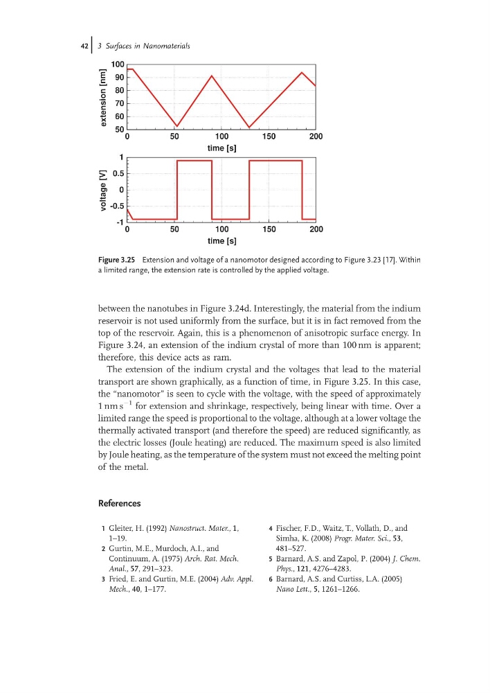
The extension of the indium crystal and the voltages that lead to the material
transport are shown graphically, as a function of time, in Figure 3.25. In this case,
the “nanomotor” is seen to cycle with the voltage, with the speed of approximately
1 nm s
À1 for extension and shrinkage, respectively, being linear with time. Over a
limited range the speed is proportional to the voltage, although at a lower voltage the
thermally activated transport (and therefore the speed) are reduced significantly, as
the electric losses (Joule heating) are reduced. The maximum speed is also limited
by Joule heating, as the temperature of the system must not exceed the melting point
of the metal.
References
1 Gleiter, H. (1992) Nanostruct. Mater., 1,
1–19.
2 Gurtin, M.E., Murdoch, A.I., and
Continuum, A. (1975) Arch. Rat. Mech.
Anal., 57, 291–323.
3 Fried, E. and Gurtin, M.E. (2004) Adv. Appl.
Mech., 40, 1–177.
4 Fischer, F.D., Waitz, T., Vollath, D., and
Simha, K. (2008) Progr. Mater. Sci., 53,
481–527.
5 Barnard, A.S. and Zapol, P. (2004) J. Chem.
Phys., 121, 4276–4283.
6 Barnard, A.S. and Curtiss, L.A. (2005)
Nano Lett., 5, 1261–1266.
0
50
100
150
200
time [s]
50
60
70
80
90
100
extension
[nm]
0
50
100
150
200
time [s]
-1
-0.5
0
0.5
1
voltage
[V]
Figure 3.25 Extension and voltage of a nanomotor designed according to Figure 3.23 [17]. Within
a limited range, the extension rate is controlled by the applied voltage.
42j 3 Surfaces in Nanomaterials
reservoir is not used uniformly from the surface, but it is in fact removed from the
top of the reservoir. Again, this is a phenomenon of anisotropic surface energy. In
Figure 3.24, an extension of the indium crystal of more than 100 nm is apparent;
therefore, this device acts as ram.
The extension of the indium crystal and the voltages that lead to the material
transport are shown graphically, as a function of time, in Figure 3.25. In this case,
the “nanomotor” is seen to cycle with the voltage, with the speed of approximately
1 nm s
À1 for extension and shrinkage, respectively, being linear with time. Over a
limited range the speed is proportional to the voltage, although at a lower voltage the
thermally activated transport (and therefore the speed) are reduced significantly, as
the electric losses (Joule heating) are reduced. The maximum speed is also limited
by Joule heating, as the temperature of the system must not exceed the melting point
of the metal.
References
1 Gleiter, H. (1992) Nanostruct. Mater., 1,
1–19.
2 Gurtin, M.E., Murdoch, A.I., and
Continuum, A. (1975) Arch. Rat. Mech.
Anal., 57, 291–323.
3 Fried, E. and Gurtin, M.E. (2004) Adv. Appl.
Mech., 40, 1–177.
4 Fischer, F.D., Waitz, T., Vollath, D., and
Simha, K. (2008) Progr. Mater. Sci., 53,
481–527.
5 Barnard, A.S. and Zapol, P. (2004) J. Chem.
Phys., 121, 4276–4283.
6 Barnard, A.S. and Curtiss, L.A. (2005)
Nano Lett., 5, 1261–1266.
0
50
100
150
200
time [s]
50
60
70
80
90
100
extension
[nm]
0
50
100
150
200
time [s]
-1
-0.5
0
0.5
1
voltage
[V]
Figure 3.25 Extension and voltage of a nanomotor designed according to Figure 3.23 [17]. Within
a limited range, the extension rate is controlled by the applied voltage.
42j 3 Surfaces in Nanomaterials