

certain limits, and to change between bright- and dark-field microscopy. Before the
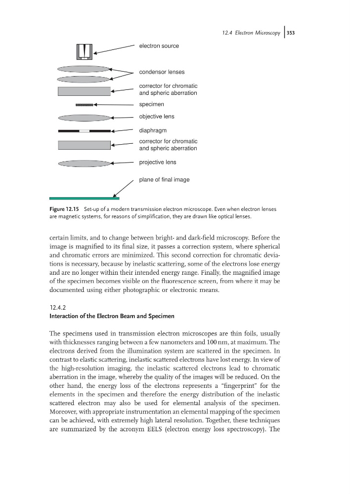
image is magnified to its final size, it passes a correction system, where spherical
and chromatic errors are minimized. This second correction for chromatic deviations is necessary, because by inelastic scattering, some of the electrons lose energy
and are no longer within their intended energy range. Finally, the magnified image
of the specimen becomes visible on the fluorescence screen, from where it may be
documented using either photographic or electronic means.
12.4.2
Interaction of the Electron Beam and Specimen
The specimens used in transmission electron microscopes are thin foils, usually
with thicknesses ranging between a few nanometers and 100 nm, at maximum. The
electrons derived from the illumination system are scattered in the specimen. In
contrast to elastic scattering, inelastic scattered electrons have lost energy. In view of
the high-resolution imaging, the inelastic scattered electrons lead to chromatic
aberration in the image, whereby the quality of the images will be reduced. On the
other hand, the energy loss of the electrons represents a “fingerprint” for the
elements in the specimen and therefore the energy distribution of the inelastic
scattered electron may also be used for elemental analysis of the specimen.
Moreover, with appropriate instrumentation an elemental mapping of the specimen
can be achieved, with extremely high lateral resolution. Together, these techniques
are summarized by the acronym EELS (electron energy loss spectroscopy). The
electron source
condensor lenses
corrector for chromatic
and spheric aberration
specimen
objective lens
diaphragm
corrector for chromatic
and spheric aberration
projective lens
plane of final image
Figure 12.15 Set-up of a modern transmission electron microscope. Even when electron lenses
are magnetic systems, for reasons of simplification, they are drawn like optical lenses.
12.4 Electron Microscopy j353
image is magnified to its final size, it passes a correction system, where spherical
and chromatic errors are minimized. This second correction for chromatic deviations is necessary, because by inelastic scattering, some of the electrons lose energy
and are no longer within their intended energy range. Finally, the magnified image
of the specimen becomes visible on the fluorescence screen, from where it may be
documented using either photographic or electronic means.
12.4.2
Interaction of the Electron Beam and Specimen
The specimens used in transmission electron microscopes are thin foils, usually
with thicknesses ranging between a few nanometers and 100 nm, at maximum. The
electrons derived from the illumination system are scattered in the specimen. In
contrast to elastic scattering, inelastic scattered electrons have lost energy. In view of
the high-resolution imaging, the inelastic scattered electrons lead to chromatic
aberration in the image, whereby the quality of the images will be reduced. On the
other hand, the energy loss of the electrons represents a “fingerprint” for the
elements in the specimen and therefore the energy distribution of the inelastic
scattered electron may also be used for elemental analysis of the specimen.
Moreover, with appropriate instrumentation an elemental mapping of the specimen
can be achieved, with extremely high lateral resolution. Together, these techniques
are summarized by the acronym EELS (electron energy loss spectroscopy). The
electron source
condensor lenses
corrector for chromatic
and spheric aberration
specimen
objective lens
diaphragm
corrector for chromatic
and spheric aberration
projective lens
plane of final image
Figure 12.15 Set-up of a modern transmission electron microscope. Even when electron lenses
are magnetic systems, for reasons of simplification, they are drawn like optical lenses.
12.4 Electron Microscopy j353