

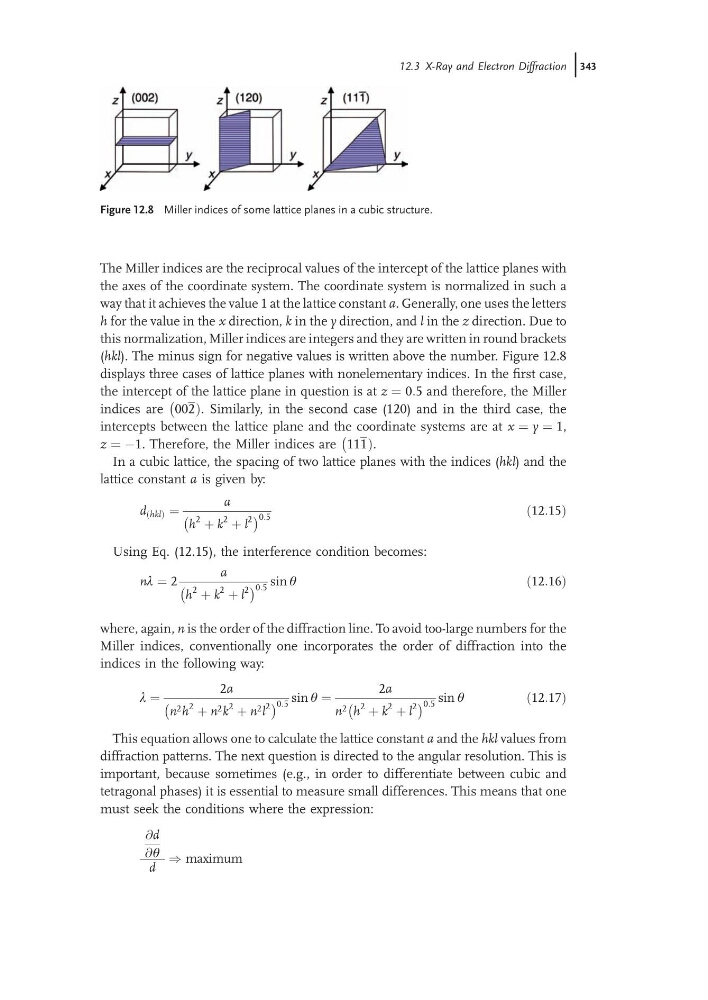
The Miller indices are the reciprocal values of the intercept of the lattice planes with
the axes of the coordinate system. The coordinate system is normalized in such a
way that it achieves the value 1 at the lattice constant a. Generally, one uses the letters
h for the value in the x direction, k in the y direction, and l in the z direction. Due to
this normalization, Miller indices are integers and they are written in round brackets
(hkl). The minus sign for negative values is written above the number. Figure 12.8
displays three cases of lattice planes with nonelementary indices. In the first case,
the intercept of the lattice plane in question is at z ¼ 0:5 and therefore, the Miller
indices are 002Þ
À
. Similarly, in the second case (120) and in the third case, the
intercepts between the lattice plane and the coordinate systems are at x ¼ y ¼ 1,
z ¼ À1. Therefore, the Miller indices are 111Þ
À
.
In a cubic lattice, the spacing of two lattice planes with the indices (hkl) and the
lattice constant a is given by:
d ðhklÞ ¼
a
h
2 þ k
2 þ l
2
À
Á 0:5
ð12:15Þ
Using Eq. (12.15), the interference condition becomes:
nl ¼ 2
a
h
2 þ k
2 þ l
2
À
Á 0:5 sin q
ð12:16Þ
where, again, n is the order of the diffraction line. To avoid too-large numbers for the
Miller indices, conventionally one incorporates the order of diffraction into the
indices in the following way:
l ¼
2a
n 2 h
2 þ n 2 k
2 þ n 2 l
2
À
Á 0:5 sin q ¼
2a
n 2 h
2 þ k
2 þ l
2
À
Á 0:5 sin q
ð12:17Þ
This equation allows one to calculate the lattice constant a and the hkl values from
diffraction patterns. The next question is directed to the angular resolution. This is
important, because sometimes (e.g., in order to differentiate between cubic and
tetragonal phases) it is essential to measure small differences. This means that one
must seek the conditions where the expression:
@d
@q
d
) maximum
Figure 12.8 Miller indices of some lattice planes in a cubic structure.
12.3 X-Ray and Electron Diffraction j343
the axes of the coordinate system. The coordinate system is normalized in such a
way that it achieves the value 1 at the lattice constant a. Generally, one uses the letters
h for the value in the x direction, k in the y direction, and l in the z direction. Due to
this normalization, Miller indices are integers and they are written in round brackets
(hkl). The minus sign for negative values is written above the number. Figure 12.8
displays three cases of lattice planes with nonelementary indices. In the first case,
the intercept of the lattice plane in question is at z ¼ 0:5 and therefore, the Miller
indices are 002Þ
À
. Similarly, in the second case (120) and in the third case, the
intercepts between the lattice plane and the coordinate systems are at x ¼ y ¼ 1,
z ¼ À1. Therefore, the Miller indices are 111Þ
À
.
In a cubic lattice, the spacing of two lattice planes with the indices (hkl) and the
lattice constant a is given by:
d ðhklÞ ¼
a
h
2 þ k
2 þ l
2
À
Á 0:5
ð12:15Þ
Using Eq. (12.15), the interference condition becomes:
nl ¼ 2
a
h
2 þ k
2 þ l
2
À
Á 0:5 sin q
ð12:16Þ
where, again, n is the order of the diffraction line. To avoid too-large numbers for the
Miller indices, conventionally one incorporates the order of diffraction into the
indices in the following way:
l ¼
2a
n 2 h
2 þ n 2 k
2 þ n 2 l
2
À
Á 0:5 sin q ¼
2a
n 2 h
2 þ k
2 þ l
2
À
Á 0:5 sin q
ð12:17Þ
This equation allows one to calculate the lattice constant a and the hkl values from
diffraction patterns. The next question is directed to the angular resolution. This is
important, because sometimes (e.g., in order to differentiate between cubic and
tetragonal phases) it is essential to measure small differences. This means that one
must seek the conditions where the expression:
@d
@q
d
) maximum
Figure 12.8 Miller indices of some lattice planes in a cubic structure.
12.3 X-Ray and Electron Diffraction j343